Upgrade your pressure monitoring game with 2513130810401 and PIC18F45K40
Beyond filters, beyond gas: Our sensors excel in every application!
Published Nov 12, 2023
Click board™
Diff Press 3 Click
Dev. board
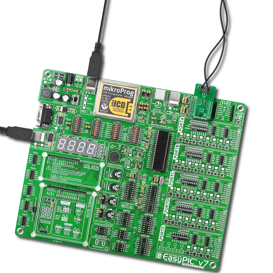
EasyPIC v7
Compiler
NECTO Studio
MCU
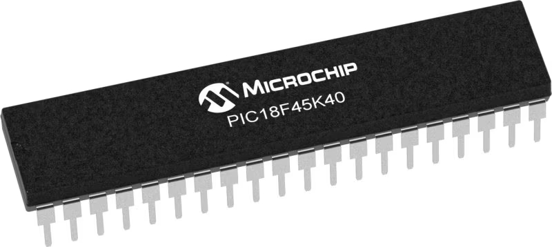
PIC18F45K40
In the world of fluid dynamics, our sensors emerge as the silent heroes, transforming pressure differentials into actionable data with unmatched precision
A
A
Hardware Overview
How does it work?
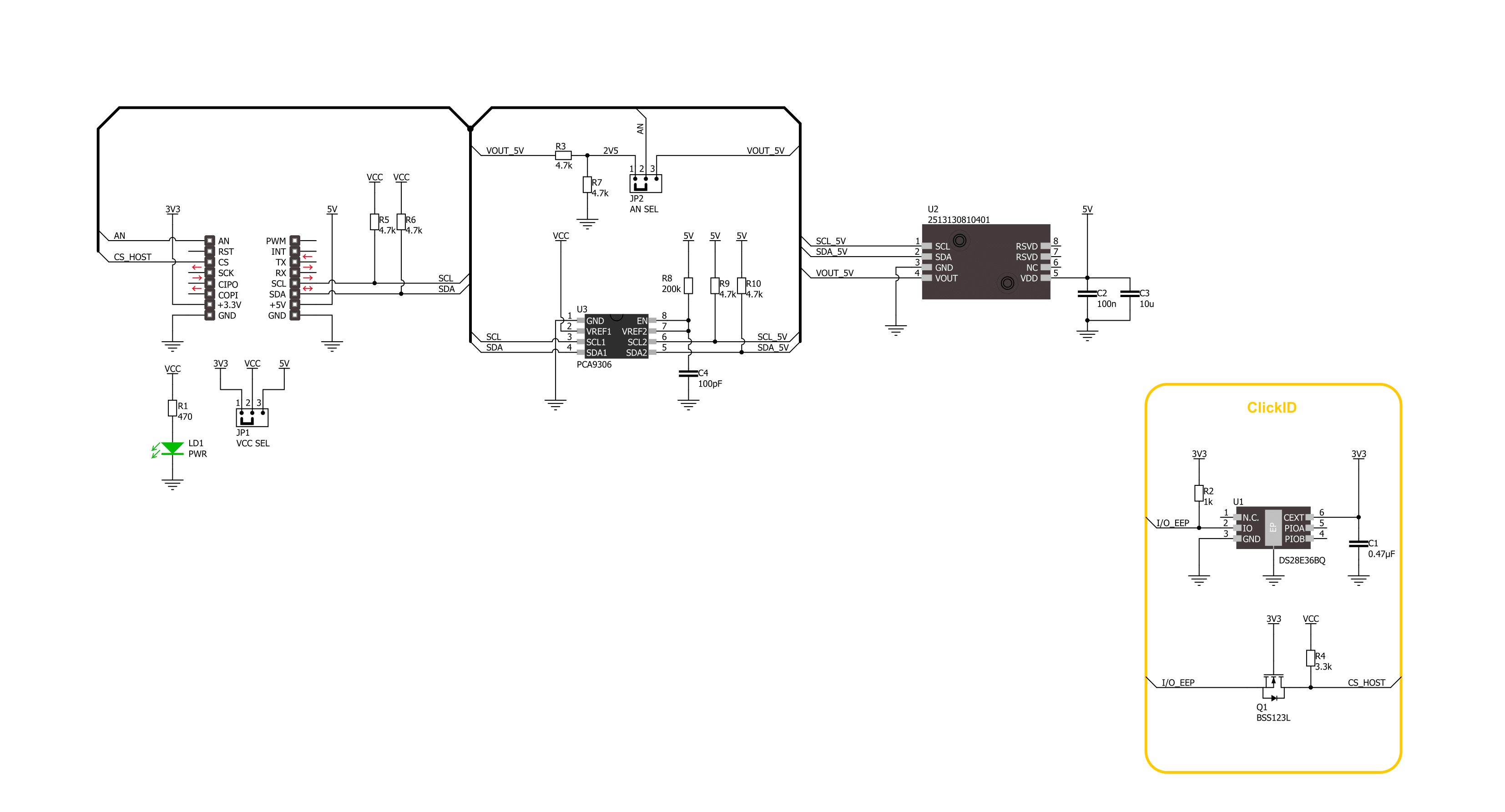
Diff Press 3 Click is based on the WSEN-PDUS ( 2513130810401 ), a differential pressure sensor from Würth Elektronik. The sensor has high accuracy, can measure different transfer pressure ranges from -100kPa up to 1000kPa, and has a response time of 2.2ms. Two pots accept ∅2.2 hoses, where one of them is a high-pressure side, and the other is designated as the vacuum side. The hoses are not included with the Diff Press 3 Click. As for temperature, this sensor can measure temperatures in a range of 0 up to 70°C and in ADC resolution of 15 bits. Diff Press 3 Click can use
a standard 2-Wire I2C interface to communicate with the host MCU, where you can read both the pressure and the temperature measurements. In addition to the I2C interface, the pressure output of the sensor can be read over the analog AN pin of the mikroBUS™ socket, where you can read only pressure measurements. As the 2513130810401 WSEN-PDUS sensor works on 5V, this Click board™ comes equipped with the PCA9306, a dual bidirectional I2C bus and SMBus voltage-level translator from Texas Instruments, which allows the use of this Click board™
with systems with 3.3V logic level. AN SEL jumper allows you to use a 5V or 2.5V logic level over a voltage divider, where 2.5V is set by default. This Click board™ can operate with either 3.3V or 5V logic voltage levels selected via the VCC SEL jumper. This way, both 3.3V and 5V capable MCUs can use the communication lines properly. Also, this Click board™ comes equipped with a library containing easy-to-use functions and an example code that can be used as a reference for further development.

Features overview
Development board
EasyPIC v7 is the seventh generation of PIC development boards specially designed to develop embedded applications rapidly. It supports a wide range of 8-bit PIC microcontrollers from Microchip and has a broad set of unique functions, such as a powerful onboard mikroProg programmer and In-Circuit debugger over USB-B. The development board is well organized and designed so that the end-user has all the necessary elements in one place, such as switches, buttons, indicators, connectors, and others. With four different connectors for each port, EasyPIC v7 allows you to connect accessory boards, sensors, and custom electronics more efficiently than ever. Each part of
the EasyPIC v7 development board contains the components necessary for the most efficient operation of the same board. An integrated mikroProg, a fast USB 2.0 programmer with mikroICD hardware In-Circuit Debugger, offers many valuable programming/debugging options and seamless integration with the Mikroe software environment. Besides it also includes a clean and regulated power supply block for the development board. It can use various external power sources, including an external 12V power supply, 7-23V AC or 9-32V DC via DC connector/screw terminals, and a power source via the USB Type-B (USB-B) connector. Communication options such as
USB-UART and RS-232 are also included, alongside the well-established mikroBUS™ standard, three display options (7-segment, graphical, and character-based LCD), and several different DIP sockets. These sockets cover a wide range of 8-bit PIC MCUs, from PIC10F, PIC12F, PIC16F, PIC16Enh, PIC18F, PIC18FJ, and PIC18FK families. EasyPIC v7 is an integral part of the Mikroe ecosystem for rapid development. Natively supported by Mikroe software tools, it covers many aspects of prototyping and development thanks to a considerable number of different Click boards™ (over a thousand boards), the number of which is growing every day.

Microcontroller Overview
MCU Card / MCU
Architecture
PIC
MCU Memory (KB)
32
Silicon Vendor
Microchip
Pin count
40
RAM (Bytes)
2048
Used MCU Pins
mikroBUS™ mapper
Take a closer look
Click board™ Schematic
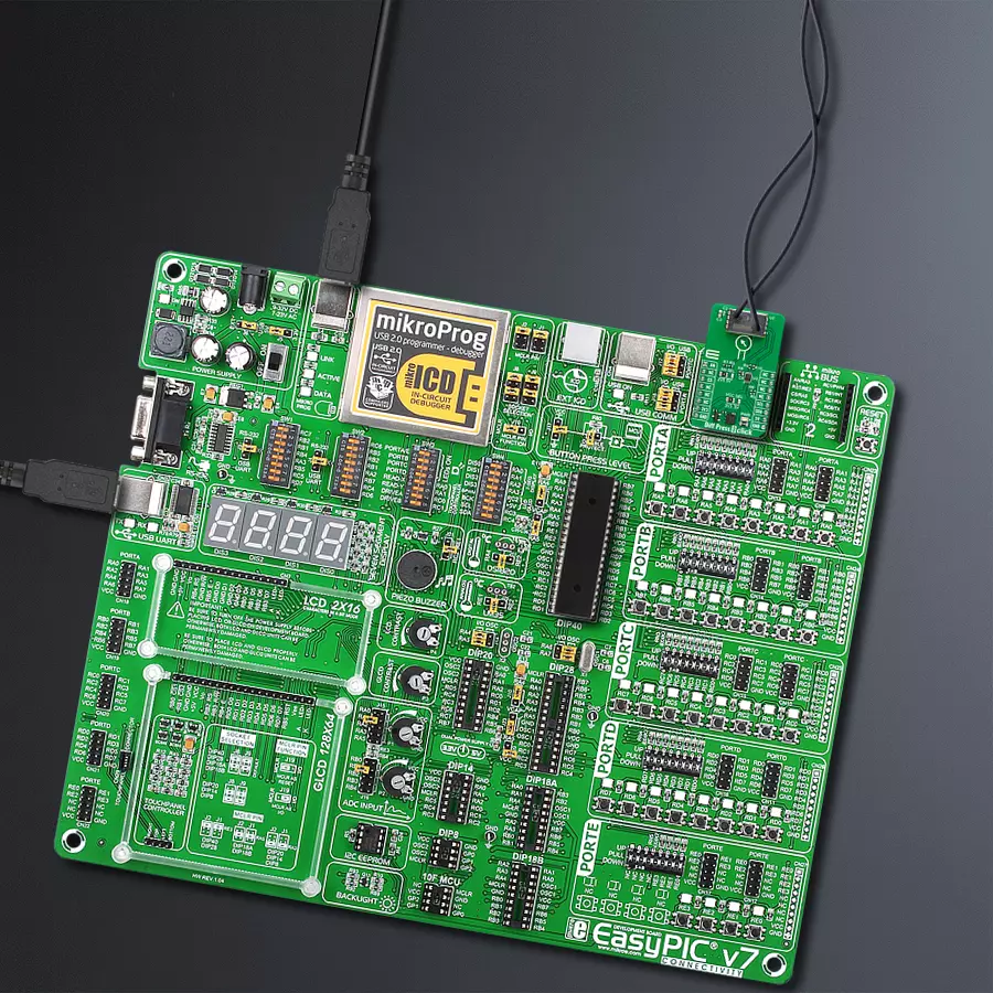
Step by step
Project assembly

Start by selecting your development board and Click board™. Begin with the EasyPIC v7 as your development board.


Track your results in real time
Application Output
1. Application Output - In Debug mode, the 'Application Output' window enables real-time data monitoring, offering direct insight into execution results. Ensure proper data display by configuring the environment correctly using the provided tutorial.

2. UART Terminal - Use the UART Terminal to monitor data transmission via a USB to UART converter, allowing direct communication between the Click board™ and your development system. Configure the baud rate and other serial settings according to your project's requirements to ensure proper functionality. For step-by-step setup instructions, refer to the provided tutorial.

3. Plot Output - The Plot feature offers a powerful way to visualize real-time sensor data, enabling trend analysis, debugging, and comparison of multiple data points. To set it up correctly, follow the provided tutorial, which includes a step-by-step example of using the Plot feature to display Click board™ readings. To use the Plot feature in your code, use the function: plot(*insert_graph_name*, variable_name);. This is a general format, and it is up to the user to replace 'insert_graph_name' with the actual graph name and 'variable_name' with the parameter to be displayed.

Software Support
Library Description
This library contains API for Diff Press 3 Click driver.
Key functions:
diffpress3_get_pressure- Diff Press 3 get pressure function.diffpress3_get_temperature- Diff Press 3 get temperature function.diffpress3_read_raw_adc- Diff Press 3 read raw ADC value function.
Open Source
Code example
The complete application code and a ready-to-use project are available through the NECTO Studio Package Manager for direct installation in the NECTO Studio. The application code can also be found on the MIKROE GitHub account.
/*!
 * @file main.c
 * @brief Diff Press 3 Click Example.
 *
 * # Description
 * This library contains API for the Diff Press 3 Click driver.
 * This demo application shows an example of
 * differential pressure and temperature measurement.
 *
 * The demo application is composed of two sections :
 *
 * ## Application Init
 * Initialization of I2C and ADC module and log UART.
 *
 * ## Application Task
 * This example demonstrates the use of the Diff Press 3 Click board™.
 * The demo application measures and display the Differential Pressure [kPa]
 * and Temperature [degree Celsius] data.
 * Results are being sent to the UART Terminal, where you can track their changes.
 *
 * @author Nenad Filipovic
 *
 */

#include "board.h"
#include "log.h"
#include "diffpress3.h"

static diffpress3_t diffpress3;   /**< Diff Press 3 Click driver object. */
static log_t logger;    /**< Logger object. */

void application_init ( void )
{
    log_cfg_t log_cfg;  /**< Logger config object. */
    diffpress3_cfg_t diffpress3_cfg;  /**< Click config object. */

    /**
     * Logger initialization.
     * Default baud rate: 115200
     * Default log level: LOG_LEVEL_DEBUG
     * @note If USB_UART_RX and USB_UART_TX
     * are defined as HAL_PIN_NC, you will
     * need to define them manually for log to work.
     * See @b LOG_MAP_USB_UART macro definition for detailed explanation.
     */
    LOG_MAP_USB_UART( log_cfg );
    log_init( &logger, &log_cfg );
    log_info( &logger, " Application Init " );

    // Click initialization.
    diffpress3_cfg_setup( &diffpress3_cfg );
    DIFFPRESS3_MAP_MIKROBUS( diffpress3_cfg, MIKROBUS_1 );
    err_t init_flag = diffpress3_init( &diffpress3, &diffpress3_cfg );
    if ( ( ADC_ERROR == init_flag ) || ( I2C_MASTER_ERROR == init_flag ) )
    {
        log_error( &logger, " Communication init." );
        for ( ; ; );
    }

    log_info( &logger, " Application Task " );
    log_printf( &logger, "---------------------\r\n" );
    Delay_ms ( 100 );
}

void application_task ( void )
{
    float pressure, temperature;
    if ( DIFFPRESS3_OK == diffpress3_get_pressure( &diffpress3, &pressure ) )
    {
        log_printf( &logger, " Diff Pressure: %.3f [kPa]\r\n", pressure );
        Delay_ms ( 100 );
    }
    if ( DIFFPRESS3_OK == diffpress3_get_temperature( &diffpress3, &temperature ) )
    {
        log_printf( &logger, " Temperature: %.2f [C]\r\n", temperature );
        Delay_ms ( 100 );
    }
    log_printf( &logger, "---------------------\r\n" );
    Delay_ms ( 1000 );
}

int main ( void )
{
    /* Do not remove this line or clock might not be set correctly. */
    #ifdef PREINIT_SUPPORTED
    preinit();
    #endif

    application_init( );

    for ( ; ; )
    {
        application_task( );
    }

    return 0;
}

// ------------------------------------------------------------------------ END


