Experience motion sensing like never before with MC3635 and PIC18LF46K80
Go beyond mere motion detection

Published Nov 01, 2023
Click board™
Accel 30 Click
Dev. board
EasyPIC v7
Compiler
NECTO Studio
MCU
PIC18LF46K80
Sensing in three dimensions has never been more magical, thanks to this 3D acceleration sensor that enhance the way you interact with the world
A
A
Hardware Overview
How does it work?
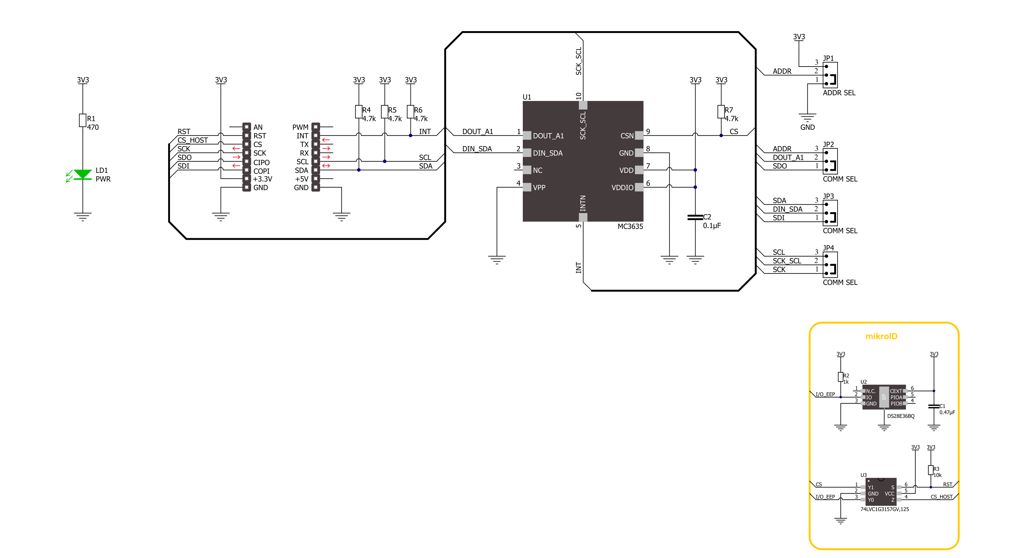
Accel 30 Click is based on the MC3635, a highly reliable digital triaxial acceleration sensor from MEMSIC. The MC3635 is highly configurable with a programmable acceleration range of ±2g, ±4g, ±8g, ±12g, or ±16g, and an internal sample rate from 14 to 1300 samples/second. It contains a 12-bit 32-sample FIFO with a programmable watermark and can be put into several operational modes, such as Sleep/Standby/Sniff/Swake/Cwake/Trig, depending upon the desired sensing application. In addition to all these features, the MC3635 is characterized by excellent temperature stability,
low noise, and low power consumption. This Click board™ allows the use of both I2C and SPI interfaces at a maximum frequency of 1MHz for I2C and 8MHz for SPI communication. Selection is made by positioning SMD jumpers marked COMM SEL to the appropriate position. All jumpers must be on the same side, or the Click board™ may become unresponsive. When the I2C interface is selected, the MC3635 allows the choice of its I2C slave address, using the ADDR SEL SMD jumper set to an appropriate position marked 0 and 1. In addition to communication pins, this board also
possesses an additional interrupt pin, routed to the INT pin on the mikroBUS™ socket, to signal MCU that an event, such as specific tap or sample acquisition conditions, has happened. This Click board™ can be operated only with a 3.3V logic voltage level. The board must perform appropriate logic voltage level conversion before using MCUs with different logic levels. Also, it comes equipped with a library containing functions and an example code that can be used as a reference for further development.


Features overview
Development board
EasyPIC v7 is the seventh generation of PIC development boards specially designed to develop embedded applications rapidly. It supports a wide range of 8-bit PIC microcontrollers from Microchip and has a broad set of unique functions, such as a powerful onboard mikroProg programmer and In-Circuit debugger over USB-B. The development board is well organized and designed so that the end-user has all the necessary elements in one place, such as switches, buttons, indicators, connectors, and others. With four different connectors for each port, EasyPIC v7 allows you to connect accessory boards, sensors, and custom electronics more efficiently than ever. Each part of
the EasyPIC v7 development board contains the components necessary for the most efficient operation of the same board. An integrated mikroProg, a fast USB 2.0 programmer with mikroICD hardware In-Circuit Debugger, offers many valuable programming/debugging options and seamless integration with the Mikroe software environment. Besides it also includes a clean and regulated power supply block for the development board. It can use various external power sources, including an external 12V power supply, 7-23V AC or 9-32V DC via DC connector/screw terminals, and a power source via the USB Type-B (USB-B) connector. Communication options such as
USB-UART and RS-232 are also included, alongside the well-established mikroBUS™ standard, three display options (7-segment, graphical, and character-based LCD), and several different DIP sockets. These sockets cover a wide range of 8-bit PIC MCUs, from PIC10F, PIC12F, PIC16F, PIC16Enh, PIC18F, PIC18FJ, and PIC18FK families. EasyPIC v7 is an integral part of the Mikroe ecosystem for rapid development. Natively supported by Mikroe software tools, it covers many aspects of prototyping and development thanks to a considerable number of different Click boards™ (over a thousand boards), the number of which is growing every day.

Microcontroller Overview
MCU Card / MCU
Architecture
PIC
MCU Memory (KB)
64
Silicon Vendor
Microchip
Pin count
40
RAM (Bytes)
3648
Used MCU Pins
mikroBUS™ mapper
Take a closer look
Click board™ Schematic
Step by step
Project assembly

Start by selecting your development board and Click board™. Begin with the EasyPIC v7 as your development board.


Software Support
Library Description
This library contains API for Accel 30 Click driver.
Key functions:
accel30_get_axis- Accel 30 get accel data functionaccel30_set_resolution_ctrl- Accel 30 set resolution control functionaccel30_set_mode- Accel 30 set operating mode function
Open Source
Code example
The complete application code and a ready-to-use project are available through the NECTO Studio Package Manager for direct installation in the NECTO Studio. The application code can also be found on the MIKROE GitHub account.
/*!
 * @file main.c
 * @brief Accel 30 Click example
 *
 * # Description
 * This library contains API for Accel 30 Click driver.
 * The library initializes and defines the I2C or SPI bus drivers
 * to write and read data from registers.
 * The library also includes a function for reading X-axis, Y-axis, and Z-axis data.
 *
 * The demo application is composed of two sections :
 *
 * ## Application Init
 * The initialization of I2C or SPI module, log UART, and additional pins.
 * After the driver init, the app executes a default configuration.
 *
 * ## Application Task
 * This example demonstrates the use of the Accel 30 Click board™.
 * Measures and displays acceleration data for X-axis, Y-axis, and Z-axis.
 * Results are being sent to the UART Terminal, where you can track their changes.
 *
 * @author Nenad Filipovic
 *
 */

#include "board.h"
#include "log.h"
#include "accel30.h"

static accel30_t accel30;
static log_t logger;

void application_init ( void )
{
    log_cfg_t log_cfg;  /**< Logger config object. */
    accel30_cfg_t accel30_cfg;  /**< Click config object. */

    /**
     * Logger initialization.
     * Default baud rate: 115200
     * Default log level: LOG_LEVEL_DEBUG
     * @note If USB_UART_RX and USB_UART_TX
     * are defined as HAL_PIN_NC, you will
     * need to define them manually for log to work.
     * See @b LOG_MAP_USB_UART macro definition for detailed explanation.
     */
    LOG_MAP_USB_UART( log_cfg );
    log_init( &logger, &log_cfg );
    log_info( &logger, " Application Init " );

    // Click initialization.
    accel30_cfg_setup( &accel30_cfg );
    ACCEL30_MAP_MIKROBUS( accel30_cfg, MIKROBUS_1 );
    err_t init_flag = accel30_init( &accel30, &accel30_cfg );
    if ( ( I2C_MASTER_ERROR == init_flag ) || ( SPI_MASTER_ERROR == init_flag ) )
    {
        log_error( &logger, " Communication init." );
        for ( ; ; );
    }

    if ( ACCEL30_ERROR == accel30_default_cfg ( &accel30 ) )
    {
        log_error( &logger, " Default configuration." );
        for ( ; ; );
    }

    log_info( &logger, " Application Task " );
    log_printf( &logger, "------------------------\r\n" );
    log_printf( &logger, "       Accel Data       \r\n" );
    log_printf( &logger, "------------------------\r\n" );
    Delay_ms ( 100 );
}

void application_task ( void )
{
    static accel30_axis_t axis;
    if ( ACCEL30_OK == accel30_get_axis( &accel30, &axis ) )
    {
        log_printf( &logger, "\tX : %d \r\n\tY : %d \r\n\tZ : %d \r\n", axis.x, axis.y, axis.z );
        log_printf( &logger, "------------------------\r\n" );
    }
    Delay_ms ( 1000 );
}

int main ( void )
{
    /* Do not remove this line or clock might not be set correctly. */
    #ifdef PREINIT_SUPPORTED
    preinit();
    #endif

    application_init( );

    for ( ; ; )
    {
        application_task( );
    }

    return 0;
}

// ------------------------------------------------------------------------ END


