Experience pH measurement at its finest with pH EZO and PIC18F4550
Your go-to expert for precise pH readings, every time

Published Nov 09, 2023
Click board™
pH Click
Dev. board
EasyPIC v7
Compiler
NECTO Studio
MCU
PIC18F4550
Count on our pH meter for reliable pH monitoring in any environment or application.
A
A
Hardware Overview
How does it work?
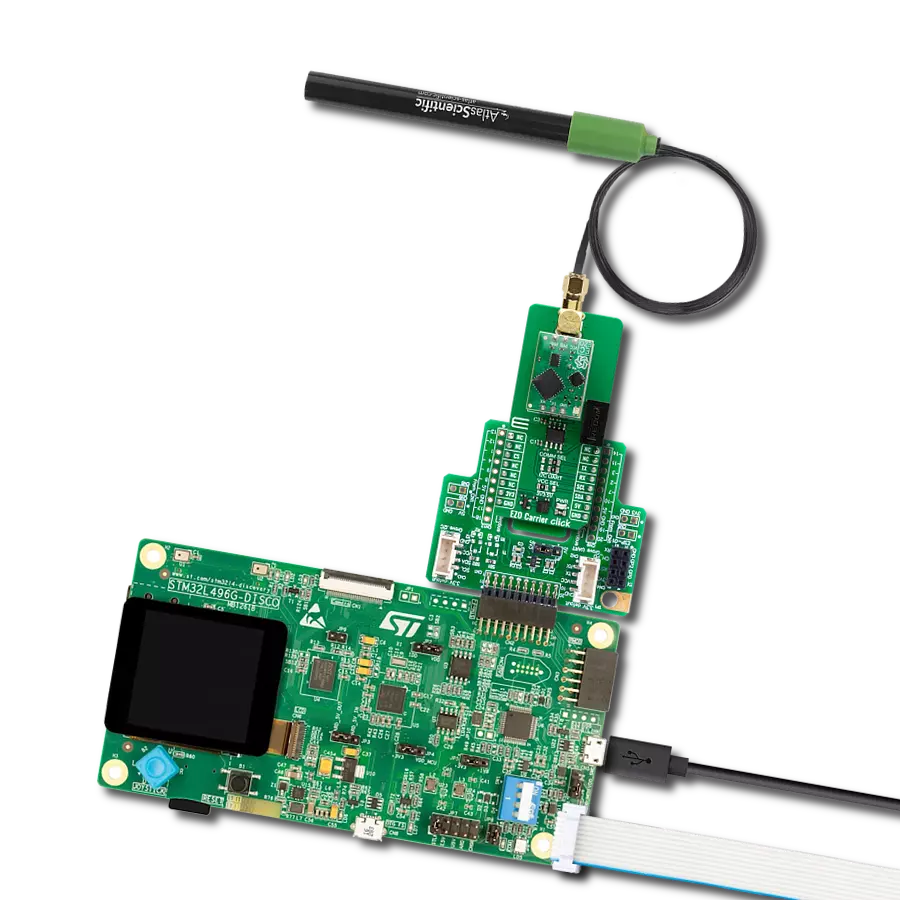
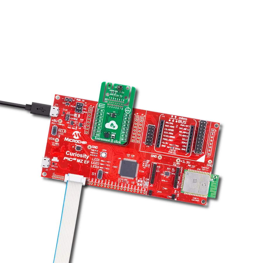
pH Click is based on the pH EZO™, a 6th-generation embedded pH circuit that offers the highest level of stability and accuracy from AtlasScientific. With an easy-to-use UART data protocol (with additional I2C serial interface), simple command structure, and flexible calibration protocol that supports single-point, two-point, or three-point calibration, this Click board™ works well with any off-the-shelf pH probe. It has temperature-dependent or independent readings with a full range of pH readings from 0.001 to 14.000. The pH EZO™ circuit is characterized by great sensitivity that gives its accuracy. When electrical noise interferes with the pH readings, it is common to see rapidly fluctuating readings or readings that are consistently off. To verify that electrical noise is causing inaccurate readings, place the pH probe in a cup of water by itself. The pH readings should
stabilize quickly, confirming that electrical noise was the issue. This Click board™ uses the UART communication interface as its default communication protocol that supports all standard baud rates up to 115.200 but also provides the possibility of using the I2C serial interface. The selection can be performed by positioning SMD jumpers labeled COMM SEL to an appropriate position. Note that all jumpers must be placed on the same side, or the Click board™ may become unresponsive. This Click Board™ uses the UART communication interface as its default communication protocol that supports all standard baud rates up to 115.200 but also provides the possibility of using the I2C serial interface. The selection can be performed by positioning SMD jumpers labeled COMM SEL to an appropriate position. Note that all jumpers must be placed on the same side, or the Click board™ may become
unresponsive. Also, the pH EZO™ circuit contains an LED indicator that informs the user about the current state of the pH circuit at any time with a specified color. The green color indicates Standby Mode, the yellow color indicates sent pH data, and the blue indicates pH data being read. Besides, there is a purple color that signals a change in the Baud rate, a red color that represents an invalid command given by the user, and a white color that the LED flashes when a device is connected to the circuit. This Click board™ can operate with either 3.3V or 5V logic voltage levels selected via the VCC SEL jumper. This way, both 3.3V and 5V capable MCUs can use the communication lines properly. Also, this Click board™ comes equipped with a library containing easy-to-use functions and an example code that can be used as a reference for further development.

Features overview
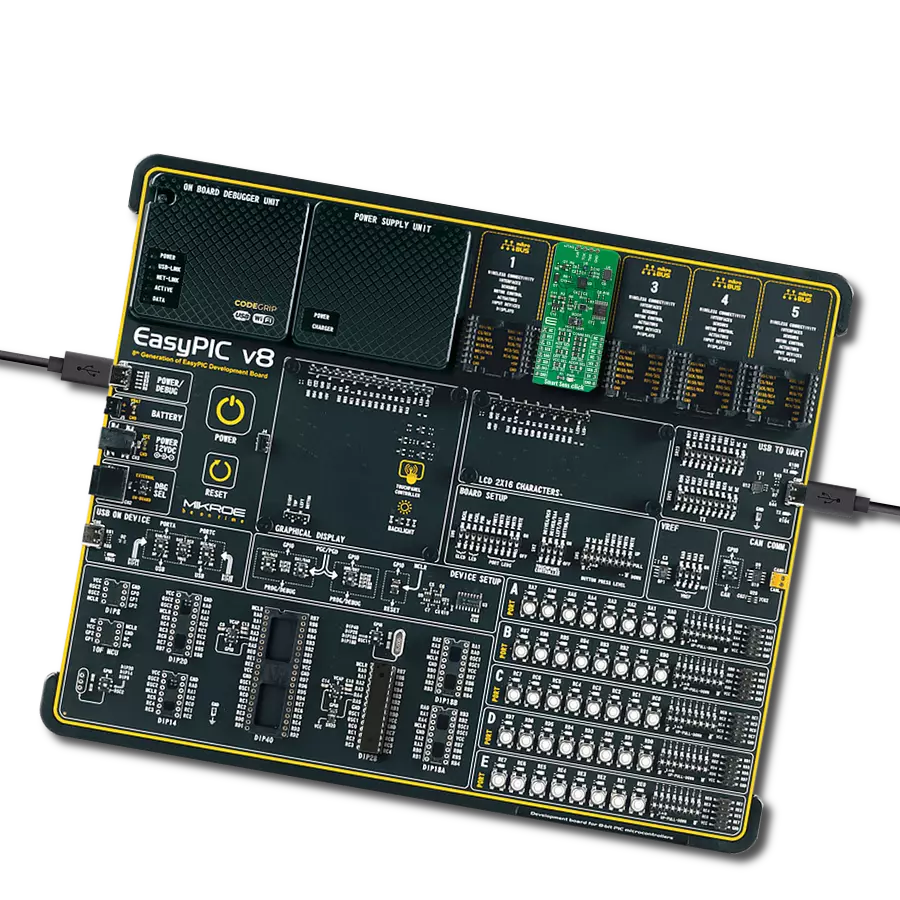
Development board
EasyPIC v7 is the seventh generation of PIC development boards specially designed to develop embedded applications rapidly. It supports a wide range of 8-bit PIC microcontrollers from Microchip and has a broad set of unique functions, such as a powerful onboard mikroProg programmer and In-Circuit debugger over USB-B. The development board is well organized and designed so that the end-user has all the necessary elements in one place, such as switches, buttons, indicators, connectors, and others. With four different connectors for each port, EasyPIC v7 allows you to connect accessory boards, sensors, and custom electronics more efficiently than ever. Each part of
the EasyPIC v7 development board contains the components necessary for the most efficient operation of the same board. An integrated mikroProg, a fast USB 2.0 programmer with mikroICD hardware In-Circuit Debugger, offers many valuable programming/debugging options and seamless integration with the Mikroe software environment. Besides it also includes a clean and regulated power supply block for the development board. It can use various external power sources, including an external 12V power supply, 7-23V AC or 9-32V DC via DC connector/screw terminals, and a power source via the USB Type-B (USB-B) connector. Communication options such as
USB-UART and RS-232 are also included, alongside the well-established mikroBUS™ standard, three display options (7-segment, graphical, and character-based LCD), and several different DIP sockets. These sockets cover a wide range of 8-bit PIC MCUs, from PIC10F, PIC12F, PIC16F, PIC16Enh, PIC18F, PIC18FJ, and PIC18FK families. EasyPIC v7 is an integral part of the Mikroe ecosystem for rapid development. Natively supported by Mikroe software tools, it covers many aspects of prototyping and development thanks to a considerable number of different Click boards™ (over a thousand boards), the number of which is growing every day.

Microcontroller Overview
MCU Card / MCU
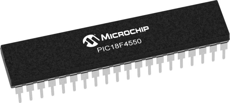
Architecture
PIC
MCU Memory (KB)
32
Silicon Vendor
Microchip
Pin count
40
RAM (Bytes)
2048
You complete me!
Accessories
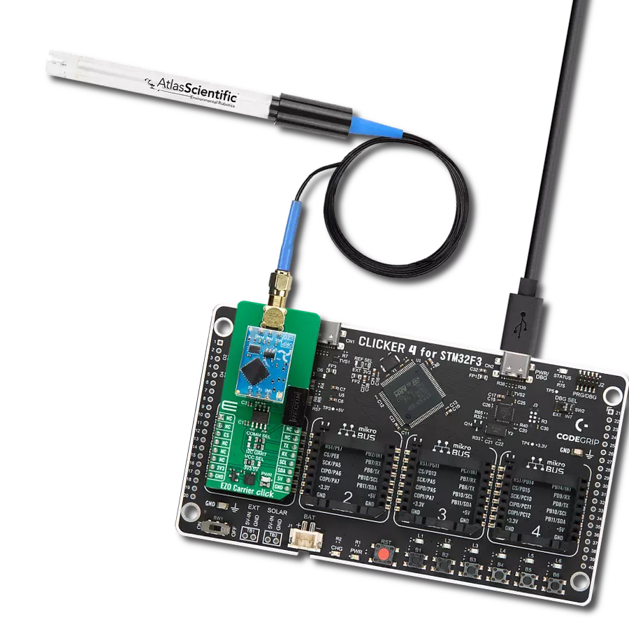
This probe can be used with all pH meters with an input for the BNC connection with a 1m cable. The sensitive part of the probe (in the shape of a ball) is partially protected by a probe's plastic body, which reduces the possibility of mechanical damage. The EPH101 is used to measure the pH value of various liquids (due to the present plastic protection), and it can also be immersed in liquids inflowed in a system). It is stored in a plastic gel bottle with a very long shelf life. A pH (potential of Hydrogen) probe measures the hydrogen ion activity in a liquid. A membrane at the tip of a pH probe permits hydrogen ions from the liquid to be measured to defuse into the outer layer of the membrane while larger ions remain in the solution. The difference in the concentration of hydrogen ions outside the probe vs. inside the pH probe creates a small current proportional to the concentration of hydrogen ions in the measured liquid.

Used MCU Pins
mikroBUS™ mapper
Take a closer look
Click board™ Schematic

Step by step
Project assembly

Start by selecting your development board and Click board™. Begin with the EasyPIC v7 as your development board.


Software Support
Library Description
This library contains API for pH Click driver.
Key functions:
ph_send_cmd- Send command function.ph_get_cmd_resp- Send get response function.ph_switch_led- Toggle LED function.
Open Source
Code example
The complete application code and a ready-to-use project are available through the NECTO Studio Package Manager for direct installation in the NECTO Studio. The application code can also be found on the MIKROE GitHub account.
/*!
 * @file main.c
 * @brief pH Click Example.
 *
 * # Description
 * This example reads and processes data from pH Clicks.
 *
 * The demo application is composed of two sections :
 *
 * ## Application Init
 * Initializes UART driver, performing a factory reset of the device, disabling continuous read,
 * and performing calibration at the midpoint on the pH scale.
 *
 * ## Application Task
 * This example shows the capabilities of the pH Click board by performing a reading of the
 * pH value of the substance in which the probe is submerged and displaying readings via the
 * USART terminal.
 *
 * @author Stefan Ilic
 *
 */

#include "board.h"
#include "log.h"
#include "ph.h"

#define PROCESS_BUFFER_SIZE 200

static ph_t ph;
static log_t logger;

static char app_buf[ PROCESS_BUFFER_SIZE ] = { 0 };

void application_init ( void )
{
    log_cfg_t log_cfg;  /**< Logger config object. */
    ph_cfg_t ph_cfg;  /**< Click config object. */

    /**
     * Logger initialization.
     * Default baud rate: 115200
     * Default log level: LOG_LEVEL_DEBUG
     * @note If USB_UART_RX and USB_UART_TX
     * are defined as HAL_PIN_NC, you will
     * need to define them manually for log to work.
     * See @b LOG_MAP_USB_UART macro definition for detailed explanation.
     */
    LOG_MAP_USB_UART( log_cfg );
    log_init( &logger, &log_cfg );
    log_info( &logger, " Application Init " );

    // Click initialization.
    ph_cfg_setup( &ph_cfg );
    PH_MAP_MIKROBUS( ph_cfg, MIKROBUS_1 );
    if ( UART_ERROR == ph_init( &ph, &ph_cfg ) )
    {
        log_error( &logger, " Communication init." );
        for ( ; ; );
    }

    ph_factory_rst( &ph, app_buf );
    Delay_ms ( 1000 );

    ph_cont_read( &ph, 0, app_buf );
    log_printf( &logger, "-----------------------\r\n" );
    log_printf( &logger, "   -- Initialized --   \r\n" );
    log_printf( &logger, "-----------------------\r\n" );
    log_printf( &logger, "  Place probe into pH  \r\n" );
    log_printf( &logger, " neutral substance for \r\n" );
    log_printf( &logger, " mid point calibration \r\n" );
    log_printf( &logger, "-----------------------\r\n" );
    for ( uint8_t n_cnt = 0; n_cnt < 20; n_cnt++ )
    {
        Delay_ms ( 1000 );
    }
    log_printf( &logger, " Starting calibration  \r\n" );
    log_printf( &logger, "-----------------------\r\n" );
    ph_perf_calib ( &ph, PH_CMD_CALIB_MID, 7.000, app_buf );
    Delay_ms ( 1000 );
    log_printf( &logger, " Calibration done!     \r\n" );
    log_printf( &logger, "-----------------------\r\n" );

    log_printf( &logger, " - Application  task -\r\n" );
    log_printf( &logger, "-----------------------\r\n" );
    ph_send_cmd( &ph, PH_CMD_DIS_RSP_CODES );
    Delay_ms ( 1000 );
    ph_clr_log_buf( app_buf );
}

void application_task ( void )
{
    ph_send_cmd ( &ph, PH_CMD_SET_SNGL_READ );
    ph_response( &ph, app_buf );
    log_printf( &logger, " pH value: %s ", app_buf );
    log_printf( &logger, "-----------------------\r\n" );
    ph_clr_log_buf( app_buf );
    Delay_ms ( 1000 );
}

int main ( void )
{
    /* Do not remove this line or clock might not be set correctly. */
    #ifdef PREINIT_SUPPORTED
    preinit();
    #endif

    application_init( );

    for ( ; ; )
    {
        application_task( );
    }

    return 0;
}

// ------------------------------------------------------------------------ END