Access real-time, reliable pressure data with DPS310 and dsPIC30F3014
Measure the world's pulse: Digital barometric sensor at your service!

Published Oct 12, 2023
Click board™
Pressure 3 Click
Dev. board
EasyPIC v7 for dsPIC30
Compiler
NECTO Studio
MCU
dsPIC30F3014
Navigate the world of meteorology and beyond with confidence, thanks to our advanced digital barometric sensor engineered for accuracy and versatility
A
A
Hardware Overview
How does it work?
Pressure 3 Click is based on the DPS310, a digital barometric pressure sensor from Infineon. This miniaturized sensor, with high accuracy and low power consumption, is capable of measuring not only the pressure but temperature as well in a range of -40 up to 85°C with a half-degree accuracy. Its sensing element is based on a capacitance sensing principle, so it achieves high precision during temperature changes. Each unit for measuring pressure and temperature is individually calibrated, and the internal signal processor converts the outputs to a 24-bit result. The calibration coefficients, stored in registers, convert measurements to high-accuracy values, both for pressure and temperature. The DPS310 integrates a FIFO (First-In-First-Out) buffer that can store the last 32 measurements, which can save power as the host MCU doesn’t have to poll
for results constantly. The DPS310 operates in three operating modes. In Standby mode, as a default mode, no measurements are performed. It is a mode after the Power-on or reset conditions in which all registers and coefficients are accessible. In Command mode (manual), the DPS310 performs one temperature and pressure measurement, after which the sensor returns to Standby mode. The measurement results are available in the data registers. In Background mode (automatic), pressure and/or temperature measurements are continuously performed according to the selected precision and rate. The DPS310 will first perform a pressure measurement and, after that, the temperature measurement. To communicate with the host MCU, the Pressure 3 Click offers a choice between two interfaces, the I2C and the SPI. The selection can be made by
positioning the SMD jumpers labeled SPI I2C to an appropriate position (I2C selected by default). Note that all the jumpers must be placed on the same side, or the Click board™ may become unresponsive. The interrupt function is available over the INT pin only while using this Click board™ via an I2C interface and can be triggered whenever a new measurement is available or if a FIFO buffer is full. This Click board™ can be operated only with a 3.3V logic voltage level. The board must perform appropriate logic voltage level conversion before using MCUs with different logic levels. Also, it comes equipped with a library containing functions and an example code that can be used as a reference for further development.


Features overview
Development board
EasyPIC v7 for dsPIC30 is the seventh generation of PIC development boards specially designed to develop embedded applications rapidly. It supports a wide range of 16-bit PIC microcontrollers from Microchip and has a broad set of unique functions, such as a powerful onboard mikroProg programmer and In-Circuit debugger over USB. The development board is well organized and designed so that the end-user has all the necessary elements in one place, such as switches, buttons, indicators, connectors, and others. With three different connectors for each port, EasyPIC v7 for dsPIC30 allows you to connect accessory boards, sensors, and custom electronics more efficiently
than ever. Each part of the EasyPIC v7 for dsPIC30 development board contains the components necessary for the most efficient operation of the same board. An integrated mikroProg, a fast USB 2.0 programmer with mikroICD hardware In-Circuit Debugger, offers many valuable programming/debugging options and seamless integration with the Mikroe software environment. Besides it also includes a clean and regulated power supply block for the development board. It can use various external power sources, including an external 12V power supply, 7-23V AC or 9-32V DC via DC connector/screw terminals, and a power source via the USB Type-B (USB-B) connector.
Communication options such as USB-UART, RS-232, and CAN are included, alongside the well-established mikroBUS™ standard, three display options (7-segment, graphical, and character-based LCD), and several different DIP sockets which cover a wide range of 16-bit dsPIC/PIC24 MCUs. EasyPIC v7 for dsPIC30 is an integral part of the Mikroe ecosystem for rapid development. Natively supported by Mikroe software tools, it covers many aspects of prototyping and development thanks to a considerable number of different Click boards™ (over a thousand boards), the number of which is growing every day.

Microcontroller Overview
MCU Card / MCU
Architecture
dsPIC
MCU Memory (KB)
24
Silicon Vendor
Microchip
Pin count
40
RAM (Bytes)
2048
Used MCU Pins
mikroBUS™ mapper
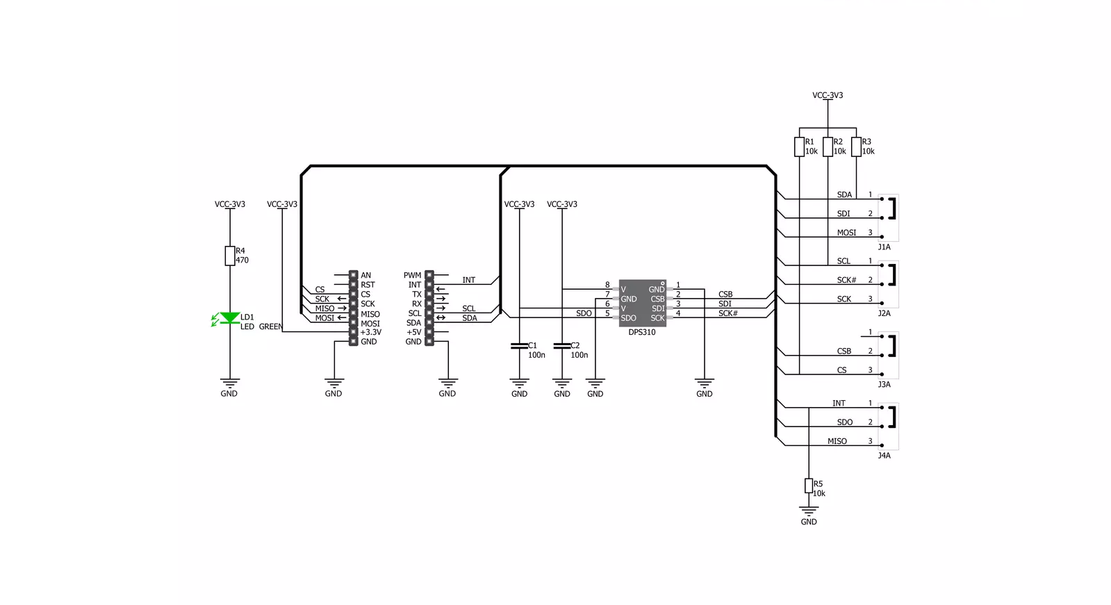
Take a closer look
Click board™ Schematic
Step by step
Project assembly

Start by selecting your development board and Click board™. Begin with the EasyPIC v7 for dsPIC30 as your development board.


Track your results in real time
Application Output
1. Application Output - In Debug mode, the 'Application Output' window enables real-time data monitoring, offering direct insight into execution results. Ensure proper data display by configuring the environment correctly using the provided tutorial.

2. UART Terminal - Use the UART Terminal to monitor data transmission via a USB to UART converter, allowing direct communication between the Click board™ and your development system. Configure the baud rate and other serial settings according to your project's requirements to ensure proper functionality. For step-by-step setup instructions, refer to the provided tutorial.

3. Plot Output - The Plot feature offers a powerful way to visualize real-time sensor data, enabling trend analysis, debugging, and comparison of multiple data points. To set it up correctly, follow the provided tutorial, which includes a step-by-step example of using the Plot feature to display Click board™ readings. To use the Plot feature in your code, use the function: plot(*insert_graph_name*, variable_name);. This is a general format, and it is up to the user to replace 'insert_graph_name' with the actual graph name and 'variable_name' with the parameter to be displayed.

Software Support
Library Description
This library contains API for Pressure 3 Click driver.
Key functions:
pressure3_get_t_p_data- Get temperature pressurepressure3_get_coefficients- Get coefficientspressure3_get_measurement_data- Read the coefficients value for calculation function
Open Source
Code example
The complete application code and a ready-to-use project are available through the NECTO Studio Package Manager for direct installation in the NECTO Studio. The application code can also be found on the MIKROE GitHub account.
/*!
 * \file
 * \brief Pressure3 Click example
 *
 * # Description
 * This application is digital barometric pressure sensor.
 *
 * The demo application is composed of two sections :
 *
 * ## Application Init
 * Initialization device, set default configuration and start to write log.
 *
 * ## Application Task
 * This is an example which demonstrates the use of Pressure 3 Click board.
     Measured pressure and temperature data from the DPS310 sensor on Pressure 3 Click board.
     Results are being sent to the Usart Terminal where you can track their changes.
     All data logs write on usb uart changes for every 3 sec.
 *
 * \author MikroE Team
 *
 */
// ------------------------------------------------------------------- INCLUDES

#include "board.h"
#include "log.h"
#include "pressure3.h"

// ------------------------------------------------------------------ VARIABLES

static pressure3_t pressure3;
static log_t logger;

static pressure3_coeff_t coeff_struct;

// ------------------------------------------------------ APPLICATION FUNCTIONS

void application_init ( )
{
    log_cfg_t log_cfg;
    pressure3_cfg_t cfg;

    /**
     * Logger initialization.
     * Default baud rate: 115200
     * Default log level: LOG_LEVEL_DEBUG
     * @note If USB_UART_RX and USB_UART_TX
     * are defined as HAL_PIN_NC, you will
     * need to define them manually for log to work.
     * See @b LOG_MAP_USB_UART macro definition for detailed explanation.
     */
    LOG_MAP_USB_UART( log_cfg );
    log_init( &logger, &log_cfg );
    log_info( &logger, "---- Application Init ----" );

    //  Click initialization.

    pressure3_cfg_setup( &cfg );
    PRESSURE3_MAP_MIKROBUS( cfg, MIKROBUS_1 );
    pressure3_init( &pressure3, &cfg );
    pressure3_default_cfg( &pressure3 );
}

void application_task ( )
{
    float pressure;
    float temperature;

    pressure3_get_t_p_data( &pressure3, &temperature, &pressure, &coeff_struct );

    log_printf( &logger, " * Pressure: %.2f mbar * \r\n", pressure );
    log_printf( &logger, " * Temperature: %.2f C * \r\n", temperature );
    log_printf( &logger, " ----------------------- \r\n" );

    Delay_ms ( 1000 );
    Delay_ms ( 1000 );
    Delay_ms ( 1000 );
}

int main ( void )
{
    /* Do not remove this line or clock might not be set correctly. */
    #ifdef PREINIT_SUPPORTED
    preinit();
    #endif

    application_init( );

    for ( ; ; )
    {
        application_task( );
    }

    return 0;
}

// ------------------------------------------------------------------------ END


