Elevate your remote monitoring capabilities with 32001345 and ATmega644P
Stay connected, no matter the distance - 868MHz transceivers at your service

Published Nov 09, 2023
Click board™
LR 3 Click
Dev. board
EasyAVR v7
Compiler
NECTO Studio
MCU
ATmega644P
Our 868MHz long-range transceiver is designed to empower your projects with seamless, low-power, and long-distance connectivity, making it ideal for remote monitoring and IoT applications.
A
A
Hardware Overview
How does it work?
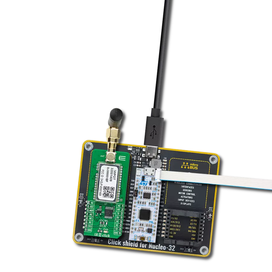
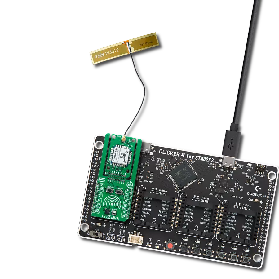
LR 3 Click is based on the 32001345, a low-power, long-range RF technology-based transceiver module from Mipot. It offers a long-range spread spectrum communication with high interference immunity. The network is implemented as a star topology, where endpoints work in duty cycle mode, significantly reducing the overall power consumption. Coupled with the AES128 message encryption and low current consumption, LR 3 Click offers an easy and reliable solution for developing low-power, highly integrated IoT networks, security systems, alarm networks, and similar applications that require simple and reliable networking solutions. This Click board™ can be configured as either END or MASTER NODE, using simple AT commands. While working as the MASTER NODE, the Click board™
can use a set of master-specific commands, such as the pairing command. This command will add the end node, which requested pairing, to the master network table. While working as the END NODE, LR 3 Click can issue slave-specific commands/requests, such as the pairing request command, allowing that end node to be paired with the master. LR 3 Click communicates with MCU using the UART interface with commonly used UART RX and TX pins at data rates up to 115200bps for data transfer. In addition to these features, the 32001345 also uses several GPIO pins connected to the mikroBUS™ socket. The WK pin routed on the CS pin of the mikroBUS™ represents the Wake-up function used for waking up the device, while the RST pin on the mikroBUS™ socket can perform a Hardware Reset
function by putting this pin in a logic low state. This Click board™ also has an indicator routed on the INT pin of the mikroBUS ™ socket, which will provide the user with feedback after a successfully received package and verified checksum. LR 3 Click features the SMA antenna connector with an impedance of 50Ω, so it can be equipped with the appropriate 868MHz compliant antenna that MIKROE offers. This Click board™ can operate with either 3.3V or 5V logic voltage levels selected via the VCC SEL jumper. This way, both 3.3V and 5V capable MCUs can use the communication lines properly. Also, this Click board™ comes equipped with a library containing easy-to-use functions and an example code that can be used as a reference for further development.

Features overview
Development board
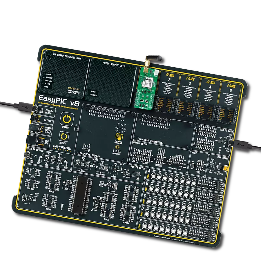
EasyAVR v7 is the seventh generation of AVR development boards specially designed for the needs of rapid development of embedded applications. It supports a wide range of 16-bit AVR microcontrollers from Microchip and has a broad set of unique functions, such as a powerful onboard mikroProg programmer and In-Circuit debugger over USB. The development board is well organized and designed so that the end-user has all the necessary elements in one place, such as switches, buttons, indicators, connectors, and others. With four different connectors for each port, EasyAVR v7 allows you to connect accessory boards, sensors, and custom electronics more
efficiently than ever. Each part of the EasyAVR v7 development board contains the components necessary for the most efficient operation of the same board. An integrated mikroProg, a fast USB 2.0 programmer with mikroICD hardware In-Circuit Debugger, offers many valuable programming/debugging options and seamless integration with the Mikroe software environment. Besides it also includes a clean and regulated power supply block for the development board. It can use a wide range of external power sources, including an external 12V power supply, 7-12V AC or 9-15V DC via DC connector/screw terminals, and a power source via the USB Type-B (USB-B)
connector. Communication options such as USB-UART and RS-232 are also included, alongside the well-established mikroBUS™ standard, three display options (7-segment, graphical, and character-based LCD), and several different DIP sockets which cover a wide range of 16-bit AVR MCUs. EasyAVR v7 is an integral part of the Mikroe ecosystem for rapid development. Natively supported by Mikroe software tools, it covers many aspects of prototyping and development thanks to a considerable number of different Click boards™ (over a thousand boards), the number of which is growing every day.

Microcontroller Overview
MCU Card / MCU

Architecture
AVR
MCU Memory (KB)
64
Silicon Vendor
Microchip
Pin count
40
RAM (Bytes)
4096
You complete me!
Accessories
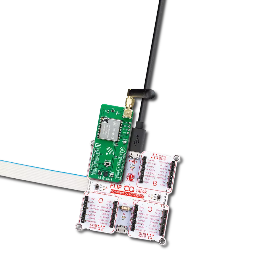
868MHz right-angle rubber antenna is a compact and versatile solution for wireless communication. Operating within the frequency range of 868-915MHz, it ensures optimal signal reception and transmission. With a 50-ohm impedance, it's compatible with various devices and systems. This antenna boasts a 2dB gain, enhancing signal strength and extending communication range. Its vertical polarization further contributes to signal clarity. Designed to handle up to 50W of input power, it's a robust choice for various applications. Measuring just 48mm in length, this antenna is both discreet and practical. Its SMA male connector ensures a secure and reliable connection to your equipment. Whether you're working with IoT devices, remote sensors, or other wireless technologies, the 868MHz right-angle antenna offers the performance and flexibility you need for seamless communication.

Used MCU Pins
mikroBUS™ mapper
Take a closer look
Click board™ Schematic

Step by step
Project assembly

Start by selecting your development board and Click board™. Begin with the EasyAVR v7 as your development board.


Software Support
Library Description
This library contains API for LR 3 Click driver.
Key functions:
lr3_factory_reset- Function performs the recovery of EEPROM default values.lr3_write_eeprom- Function writes data to EEPROM.lr3_tx_message- Function performs the transmission of radio frames.
Open Source
Code example
The complete application code and a ready-to-use project are available through the NECTO Studio Package Manager for direct installation in the NECTO Studio. The application code can also be found on the MIKROE GitHub account.
/*!
 * \file
 * \brief LR3 Click example
 *
 * # Description
 * This example reads and processes data from LR 3 Clicks.
 *
 * The demo application is composed of two sections :
 *
 * ## Application Init
 * Initializes the driver, enables the Click board and configures it for the selected mode.
 *
 * ## Application Task
 * Depending on the selected mode, it reads all the received data or sends a desired message
 * every 3 seconds. All data is being displayed on the USB UART.
 *
 * ## Additional Function
 * - indication_handler - Logs results on USB UART when device gets indication status.
 *
 * \author MikroE Team
 *
 */
// ------------------------------------------------------------------- INCLUDES

#include "board.h"
#include "log.h"
#include "lr3.h"
#include "string.h"

// ------------------------------------------------------------------ VARIABLES

#define MASTER
// #define END_NODE

#define TEXT_TO_SEND "MikroE"

static lr3_t lr3;
static lr3_tx_msg_t lr3_tx_msg;
static log_t logger;

static lr3_message_t tmp_msg;

// -------------------------------------------------------- ADDITIONAL FUNCTIONS

static void indication_handler( uint8_t *cmd, uint8_t *pl_size, uint8_t *pl_buffer )
{
    if ( *cmd == LR3_INDICATES_RX_MSG )
    {
        if ( pl_buffer[ 0 ] == 0x00 )
        {
            log_printf( &logger, "Message received!\r\n" );
            int16_t rssi = ( pl_buffer[ 2 ] << 8 ) | pl_buffer[ 1 ];
            log_printf( &logger, "RSSI in dBm: %d\r\n", rssi );
            log_printf( &logger, "Signal-to-Noise Ratio: %u\r\n", ( uint16_t ) pl_buffer[ 3 ] );
            log_printf( &logger, "Source ID: 0x%.2X%.2X%.2X%.2X\r\n", ( uint16_t ) pl_buffer[ 7 ],
                                                                      ( uint16_t ) pl_buffer[ 6 ],
                                                                      ( uint16_t ) pl_buffer[ 5 ],
                                                                      ( uint16_t ) pl_buffer[ 4 ] );
            log_printf( &logger, "Message content: " );
            for ( uint8_t cnt = 8; cnt < *pl_size; cnt++ )
            {
                log_printf( &logger, "%c", ( uint16_t ) pl_buffer[ cnt ] );
            }
            log_printf( &logger, "\r\nChecksum: %u", ( uint16_t ) pl_buffer[ *pl_size ] );
            log_printf( &logger, "\r\n------------------------\r\n" );
        }
        else
        {
            log_printf( &logger, "Error!\r\n" );
        }
    }
    else
    {
        log_printf( &logger, "IND TYPE: 0x%.2X\r\n", ( uint16_t ) *cmd );
        log_printf( &logger, "PAYLOAD : " );

        for ( uint8_t cnt = 0; cnt <= *pl_size; cnt++ )
        {
            log_printf( &logger, "0x%.2X ", ( uint16_t ) pl_buffer[ cnt ] );
        }
        log_printf( &logger, "\r\n------------------------\r\n" );
    }

}

// ------------------------------------------------------ APPLICATION FUNCTIONS

void application_init ( void )
{
    log_cfg_t log_cfg;
    lr3_cfg_t cfg;

    /**
     * Logger initialization.
     * Default baud rate: 115200
     * Default log level: LOG_LEVEL_DEBUG
     * @note If USB_UART_RX and USB_UART_TX
     * are defined as HAL_PIN_NC, you will
     * need to define them manually for log to work.
     * See @b LOG_MAP_USB_UART macro definition for detailed explanation.
     */
    LOG_MAP_USB_UART( log_cfg );
    log_init( &logger, &log_cfg );
    log_info( &logger, "---- Application Init ----" );

    //  Click initialization.

    lr3_cfg_setup( &cfg );
    LR3_MAP_MIKROBUS( cfg, MIKROBUS_1 );
    lr3_init( &lr3, &cfg );

    Delay_ms ( 100 );
    lr3_set_ind_handler( &lr3, indication_handler );
    lr3_hard_reset( &lr3 );
    lr3_factory_reset( &lr3 );
    Delay_ms ( 1000 );

#ifdef MASTER
    // Set device as MASTER
    tmp_msg.payload[ 0 ] = 0;

    if( lr3_write_eeprom( &lr3, 0x00, 1, &tmp_msg.payload[ 0 ] ) )
    {
        log_error( &logger, "Setting device as MASTER!\r\n" );
        for( ; ; );
    }

    log_printf( &logger, "Device configured as MASTER!\r\n" );
    Delay_ms ( 1000 );

    // Delete all network table
    if( lr3_delete_all_network_table( &lr3 ) )
    {
        log_error( &logger, "Deleting all paired devices!\r\n" );
        for( ; ; );
    }
    log_printf( &logger, "All paired devices deleted!\r\n" );
    Delay_ms ( 1000 );

    // Enable pairing
    if( lr3_enable_pairing( &lr3, 1 ) )
    {
        log_error( &logger, "Pairing not enabled!\r\n" );
        for( ; ; );
    }
    log_printf( &logger, "Pairing enabled!\r\n" );
    Delay_ms ( 1000 );
#endif

#ifdef END_NODE
    // Set device as END_NODE
    tmp_msg.payload[ 0 ] = 1;

    if( lr3_write_eeprom( &lr3, 0x00, 1, &tmp_msg.payload[ 0 ] ) )
    {
        log_error( &logger, "Setting device as END_NODE!\r\n" );
        for( ; ; );
    }

    log_printf( &logger, "Device configured as END_NODE!\r\n" );
    Delay_ms ( 1000 );

    // Send pairing request and displays MASTER ID
    uint8_t master_id[ 4 ] = { 0 };
    do
    {
        lr3_get_pairing_request( &lr3 );
        Delay_ms ( 1000 );
    }
    while ( lr3_get_activation_status( &lr3, master_id ) != 1 );
    log_printf( &logger, "Paired to a network!\r\n" );
    log_printf( &logger, "Master ID: 0x%.2X%.2X%.2X%.2X\r\n", ( uint16_t ) master_id[ 3 ],
                                                              ( uint16_t ) master_id[ 2 ],
                                                              ( uint16_t ) master_id[ 1 ],
                                                              ( uint16_t ) master_id[ 0 ] );

#endif
}

void application_task ( void )
{
#ifdef END_NODE
    strcpy( tmp_msg.payload, TEXT_TO_SEND );

    lr3_tx_msg.data_in = &tmp_msg.payload[ 0 ];
    lr3_tx_msg.n_bytes = strlen( TEXT_TO_SEND );
    lr3_tx_msg.destination_id = LR3_BROADCAST_MESSAGE;
    lr3_tx_msg.option = LR3_UNCONFIRMED_DATA_TX;
    if ( lr3_tx_message( &lr3, &lr3_tx_msg ) == 0 )
    {
        log_printf( &logger, "Message: \"%s\" sent to MASTER...\r\n", ( uint8_t * ) TEXT_TO_SEND );
        log_printf( &logger, "------------------------\r\n" );
    }

    Delay_ms ( 1000 );
    Delay_ms ( 1000 );
    Delay_ms ( 1000 );
#endif
#ifdef MASTER
    lr3_read_message_process( &lr3 );
#endif
}

int main ( void )
{
    /* Do not remove this line or clock might not be set correctly. */
    #ifdef PREINIT_SUPPORTED
    preinit();
    #endif

    application_init( );

    for ( ; ; )
    {
        application_task( );
    }

    return 0;
}


// ------------------------------------------------------------------------ END