Mastering pressure dynamics using ABPLLNN600MGAA3 and ATmega32
Digital pressure sensor: A game-changer for engineering excellence

Published Nov 01, 2023
Click board™
Pressure 12 Click
Dev. board
EasyAVR v7
Compiler
NECTO Studio
MCU
ATmega32
Engineered for excellence, our digital pressure measurement solution is your partner in achieving consistent and reliable results in challenging environments
A
A
Hardware Overview
How does it work?
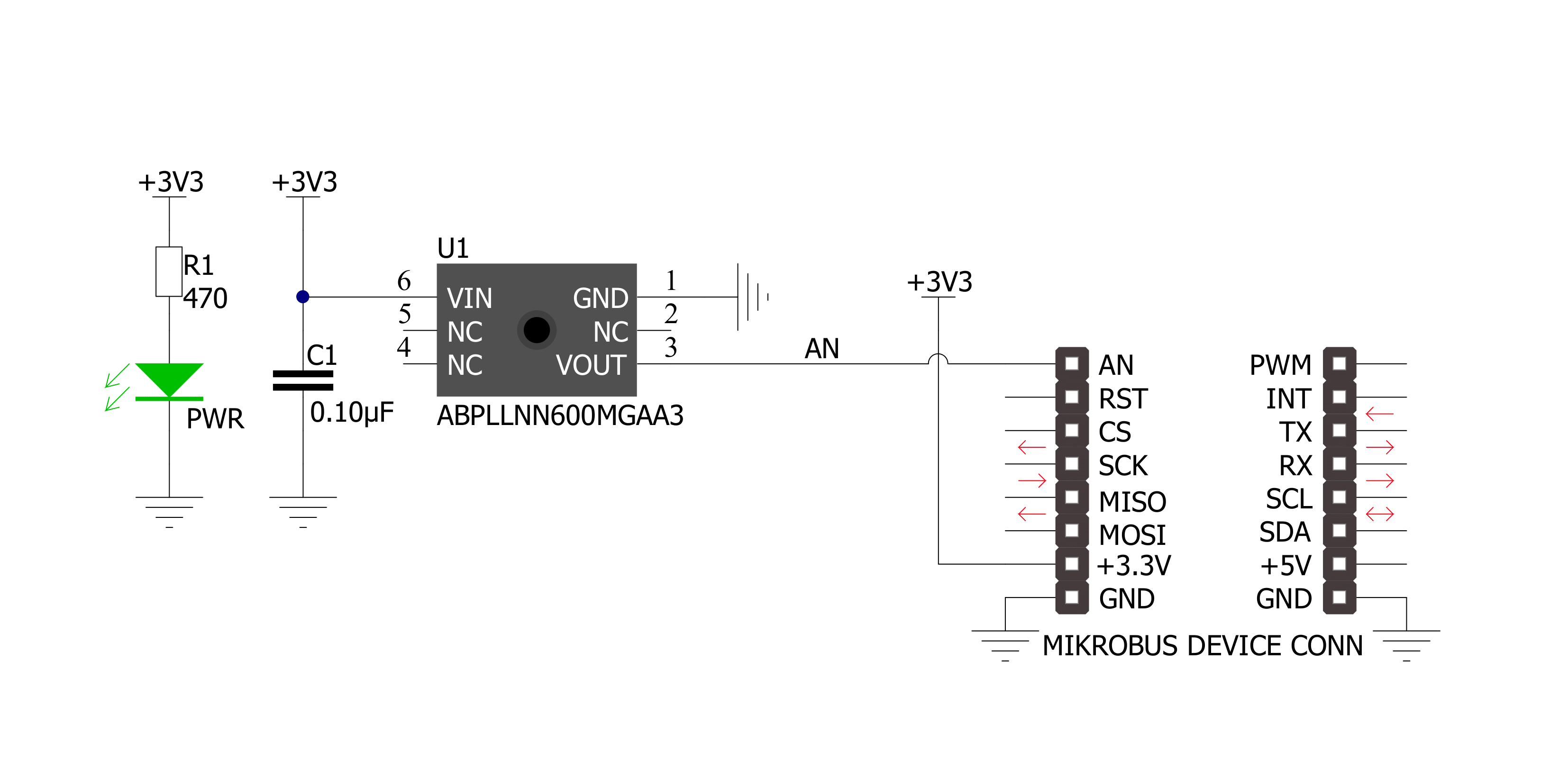
Pressure 12 Click is based on the ABPLLNN600MGAA3, an ABP series gauge pressure sensor from Honeywell. The entire ABP series sensors are very similar in design, so minor differences specific for a particular sensor are actually encoded into its label. The ABP series datasheet offers a detailed explanation of each code of the label. The specific sensor used on the Pressure 12 click is a piezoresistive silicon pressure sensor, which can be used for non-corrosive and non-ionic dry gas media and should not be exposed to moisture and corrosion. The sensor itself is based on a piezoresistive silicon membrane sensitive to pressure, which is backed up by an ASIC. The ASIC applies temperature compensation and calibration to the signal. The ratiometric voltage at the output pin is updated once per one ms (1kHz), allowing it to be used either by the A/D converter of the host MCU or directly within the control feedback loop, ensuring the least possible
latency. The thermal compensation covers the range between 0⁰C and 50 ⁰C, where the sensor has the smallest TEB value. The datasheet introduces TEB (Total Error Band) term as the most realistic representation of the sensor's accuracy, taking many factors into an account, including errors caused by the offset, hysteresis, non-linearity, and other factors… Honeywell uses the TEB to illustrate the overall sensor's accuracy, since no single parameter can exist without being influenced by some other parameters (thermal effect on the offset, hysteresis, just to name few). This helps to paint a more realistic picture of the sensor's performance. The sensor contains a single axial barbless port, adequate for secure interfacing with various pipes, hoses or gas-filled containers of some pressurized system which needs to be controlled or monitored. No barbed port is required for this sensor, as the maximum gauge pressure, it can measure goes up to 600mbar. The
voltage at the output changes proportionally with the applied pressure. The ABP series datasheet provides a simple conversion formula, which can be used to calculate the pressure value for a given output voltage. This formula is simple to be calculated by the firmware that runs on the host MCU, as the output voltage is already conditioned by the sensor's ASIC. Since the sensor uses only an analog output voltage, which changes proportionally with the applied pressure (as described previously), there are no setup registers, or any user-configurable parameters. However, the Click board™ is supported by a mikroSDK compatible library with functions that allow using an internal ADC module of the MCU, and an example that demonstrates their use. The demo example utilizes the aforementioned conversion formula to output pressure value based on the sensor's output voltage.


Features overview
Development board
EasyAVR v7 is the seventh generation of AVR development boards specially designed for the needs of rapid development of embedded applications. It supports a wide range of 16-bit AVR microcontrollers from Microchip and has a broad set of unique functions, such as a powerful onboard mikroProg programmer and In-Circuit debugger over USB. The development board is well organized and designed so that the end-user has all the necessary elements in one place, such as switches, buttons, indicators, connectors, and others. With four different connectors for each port, EasyAVR v7 allows you to connect accessory boards, sensors, and custom electronics more
efficiently than ever. Each part of the EasyAVR v7 development board contains the components necessary for the most efficient operation of the same board. An integrated mikroProg, a fast USB 2.0 programmer with mikroICD hardware In-Circuit Debugger, offers many valuable programming/debugging options and seamless integration with the Mikroe software environment. Besides it also includes a clean and regulated power supply block for the development board. It can use a wide range of external power sources, including an external 12V power supply, 7-12V AC or 9-15V DC via DC connector/screw terminals, and a power source via the USB Type-B (USB-B)
connector. Communication options such as USB-UART and RS-232 are also included, alongside the well-established mikroBUS™ standard, three display options (7-segment, graphical, and character-based LCD), and several different DIP sockets which cover a wide range of 16-bit AVR MCUs. EasyAVR v7 is an integral part of the Mikroe ecosystem for rapid development. Natively supported by Mikroe software tools, it covers many aspects of prototyping and development thanks to a considerable number of different Click boards™ (over a thousand boards), the number of which is growing every day.

Microcontroller Overview
MCU Card / MCU

Architecture
AVR
MCU Memory (KB)
32
Silicon Vendor
Microchip
Pin count
40
RAM (Bytes)
2048
Used MCU Pins
mikroBUS™ mapper
Take a closer look
Click board™ Schematic
Step by step
Project assembly

Start by selecting your development board and Click board™. Begin with the EasyAVR v7 as your development board.


Software Support
Library Description
This library contains API for Pressure 12 Click driver.
Key functions:
pressure12_get_pressure- Get pressure functionpressure12_get_voltage- Get voltage functionpressure12_set_adc_resolution- Set ADC resolution function
Open Source
Code example
The complete application code and a ready-to-use project are available through the NECTO Studio Package Manager for direct installation in the NECTO Studio. The application code can also be found on the MIKROE GitHub account.
/*!
 * \file
 * \brief Pressure12 Click example
 *
 * # Description
 * Reads ADC value, convert ADC data to Voltage[ mV ] and pressure [ mBar ].
 *
 * The demo application is composed of two sections :
 *
 * ## Application Init
 * Initializes ADC and LOG for logging data.
 *
 * ## Application Task
 * Reads ADC value, convert ADC data to Voltage[ mV ] on the AN pin and
 * convert to Pressure data in mBar. All data logs to the USBUART each second.
 *
 * ## NOTE
 * Output is proportional to the difference between applied pressure
 * and atmospheric (ambient) pressure.
 *
 * \author Luka Filipovic
 *
 */
// ------------------------------------------------------------------- INCLUDES

#include "board.h"
#include "log.h"
#include "pressure12.h"

// ------------------------------------------------------------------ VARIABLES

static pressure12_t pressure12;
static log_t logger;

static uint16_t pressure_val;
static float voltage_val;

// ------------------------------------------------------ APPLICATION FUNCTIONS

void application_init ( void )
{
    log_cfg_t log_cfg;
    pressure12_cfg_t cfg;

    /**
     * Logger initialization.
     * Default baud rate: 115200
     * Default log level: LOG_LEVEL_DEBUG
     * @note If USB_UART_RX and USB_UART_TX
     * are defined as HAL_PIN_NC, you will
     * need to define them manually for log to work.
     * See @b LOG_MAP_USB_UART macro definition for detailed explanation.
     */
    LOG_MAP_USB_UART( log_cfg );
    log_init( &logger, &log_cfg );
    log_info( &logger, "---- Application Init ----" );

    //  Click initialization.

    pressure12_cfg_setup( &cfg );
    PRESSURE12_MAP_MIKROBUS( cfg, MIKROBUS_1 );
    if ( pressure12_init( &pressure12, &cfg ) == ADC_ERROR )
    {
        log_info( &logger, "---- Application Init Error ----" );
        log_info( &logger, "---- Please, run program again ----" );

        for ( ; ; );
    }
    log_info( &logger, "---- Application Init Done ----\r\n" );

    pressure_val = 0;
    voltage_val = 0;
}

void application_task ( void )
{
    if ( pressure12_read_pin_voltage( &pressure12, &voltage_val ) != ADC_ERROR )
    {
        log_printf( &logger, " Voltage [V] : %.2f\r\n", voltage_val );
    }

    if ( pressure12_get_pressure( &pressure12, &pressure_val ) != ADC_ERROR )
    {
        log_printf( &logger, " Pressure [mBar] : %u\r\n", pressure_val );
    }

    log_printf( &logger, "-----------------------------\r\n" );
    Delay_ms ( 1000 );
}

int main ( void )
{
    /* Do not remove this line or clock might not be set correctly. */
    #ifdef PREINIT_SUPPORTED
    preinit();
    #endif

    application_init( );

    for ( ; ; )
    {
        application_task( );
    }

    return 0;
}


// ------------------------------------------------------------------------ END


