Allow devices to draw power from USB Type-C ports with CYPD3178 and ATmega644P
Highly-integrated pre-programmed USB Type-C sink port controller

Published Oct 16, 2024
Click board™
USB-C Sink 4 Click
Dev. board
EasyAVR v7
Compiler
NECTO Studio
MCU
ATmega644P
Enable charging for various rechargeable devices with USB Type-C ports
A
A
Hardware Overview
How does it work?
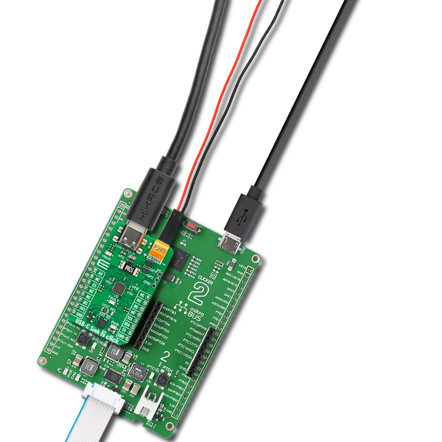
USB-C Sink 4 Click is based on the CYPD3178, a USB Type-C power sink controller from Infineon. This controller replaces traditional barrel connectors, allowing devices to draw power through the more versatile and standardized USB Type-C interface. The CYPD3178 is part of Infineon's Barrel Connector Replacement (BCR) family and complies with the latest USB Type-C specifications, supporting power delivery of up to 5V at 3A. What makes the CYPD3178 stand out is its ability to convert devices from barrel-powered to USB Type-C-powered with minimal additional components and no need for further firmware development. The integrated solution includes a full USB Type-C transceiver, load switch control with a soft start feature, and all the necessary termination resistors for seamless USB Type-C port operation. It also provides system-level fault protection and Electrostatic Discharge (ESD) safeguards, ensuring robust performance in various environments. This Click board™ is perfect for powering electronic devices such as drones, smart speakers, power tools, and other rechargeable gadgets, making it a versatile and reliable power management solution. The CYPD3178 on the USB-C Sink 4 Click supports multiple charging protocols. When connected to a non-PD charger, it can negotiate with any legacy charging protocol supported by the sink device. The CHG SEL jumper allows users to configure the supported protocols. The jumper is set to the LGC position by default, enabling support for all legacy charging protocols. However, by
switching the jumper to the BC1.2 position, the device limits its operation to the BC1.2 charging protocol only. The board's VBUS MIN and VBUS MAX jumpers determine the minimum and maximum voltages that the CYPD3178 will negotiate. VBUS_MIN is set to 5V by default, while a 5-position jumper allows users to configure the VBUS_MAX value. The USB-C standard supports various voltage levels, ranging from 5V to 20V, depending on the agreed "power contract" between the device and the charger. Adjusting the VBUS MAX jumper to the appropriate position enables the desired voltage level. The green VBUS LED indicates the presence of power on the USB-C port. Similarly, the ISNK FNE and CRS resistor dividers configure the operating current communicated to the Type-C power adapter. The operating current (ISNK) is the sum of the currents these resistor dividers specify. The USB-C Sink 4 Click features an unpopulated SAFE 5V header that can be used to drive an alternate load. This header becomes active whenever the CYPD3178 cannot negotiate the higher requested power contract (e.g., 9V or 15V, for example). In such cases, the CYPD3178 negotiates a 5V power supply, which can be delivered to an alternate power rail within the system through this header. This enables the system to continue operating in a limited mode when the desired higher power is unavailable through the USB Type-C port. USB-C Sink 4 Click uses a standard 2-wire I2C interface to communicate with the host MCU, supporting a
maximum clock frequency of 400kHz. In addition to the I2C pins, it features an active-low INT interrupt pin, used to notify the MCU of important events, such as changes in the power status. The INT and FLT pins can also serve a secondary purpose for debugging, acting as SWD_DAT (INT) and SWD_CLK (FLT) pins, accessible through the unpopulated DBG header for debugging purposes. The red FLT LED indicator on USB-C Sink 4 Click turns ON when certain conditions are met, such as when a power negotiation contract cannot be established or when none of the offered voltages fall within the VBUS_MIN and VBUS_MAX ranges. Additionally, the LED will light up if the load draws more current than the expected threshold (Sink OCP). In addition to visual identification, this fault signal can also be tracked digitally through the FLT pin on the mikroBUS™ socket. The USB-C Sink 4 Click includes two test points for monitoring key signals. TP1 measures and monitors the VBUS voltage, while TP2 (FLP) helps determine the data mode and orientation of the USB Type-C cable, specifically whether the USB CC polarity is flipped. By default, the TP2 signal is pulled up with a 1kΩ resistor for non-data communication applications. This Click board™ can be operated only with a 3.3V logic voltage level. The board must perform appropriate logic voltage level conversion before using MCUs with different logic levels. Also, it comes equipped with a library containing functions and an example code that can be used as a reference for further development.

Features overview
Development board
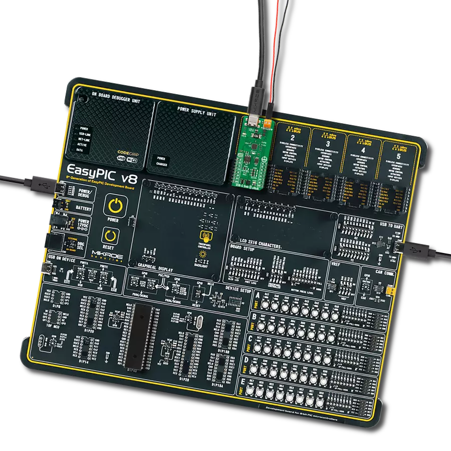
EasyAVR v7 is the seventh generation of AVR development boards specially designed for the needs of rapid development of embedded applications. It supports a wide range of 16-bit AVR microcontrollers from Microchip and has a broad set of unique functions, such as a powerful onboard mikroProg programmer and In-Circuit debugger over USB. The development board is well organized and designed so that the end-user has all the necessary elements in one place, such as switches, buttons, indicators, connectors, and others. With four different connectors for each port, EasyAVR v7 allows you to connect accessory boards, sensors, and custom electronics more
efficiently than ever. Each part of the EasyAVR v7 development board contains the components necessary for the most efficient operation of the same board. An integrated mikroProg, a fast USB 2.0 programmer with mikroICD hardware In-Circuit Debugger, offers many valuable programming/debugging options and seamless integration with the Mikroe software environment. Besides it also includes a clean and regulated power supply block for the development board. It can use a wide range of external power sources, including an external 12V power supply, 7-12V AC or 9-15V DC via DC connector/screw terminals, and a power source via the USB Type-B (USB-B)
connector. Communication options such as USB-UART and RS-232 are also included, alongside the well-established mikroBUS™ standard, three display options (7-segment, graphical, and character-based LCD), and several different DIP sockets which cover a wide range of 16-bit AVR MCUs. EasyAVR v7 is an integral part of the Mikroe ecosystem for rapid development. Natively supported by Mikroe software tools, it covers many aspects of prototyping and development thanks to a considerable number of different Click boards™ (over a thousand boards), the number of which is growing every day.

Microcontroller Overview
MCU Card / MCU

Architecture
AVR
MCU Memory (KB)
64
Silicon Vendor
Microchip
Pin count
40
RAM (Bytes)
4096
You complete me!
Accessories
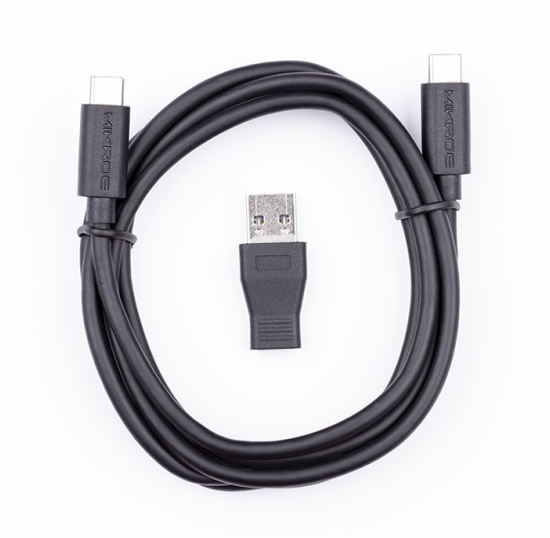
This is a USB 3.1 cable with USB Type C male connectors on both sides. Cable comes with USB Type C Female to USB Type A Male adapter, making it compabitle with USB 2.0 and USB 3.0 host slots as well. Cable is 1.5 meters long and compatible with any USB type C development tools.
Used MCU Pins
mikroBUS™ mapper
Take a closer look
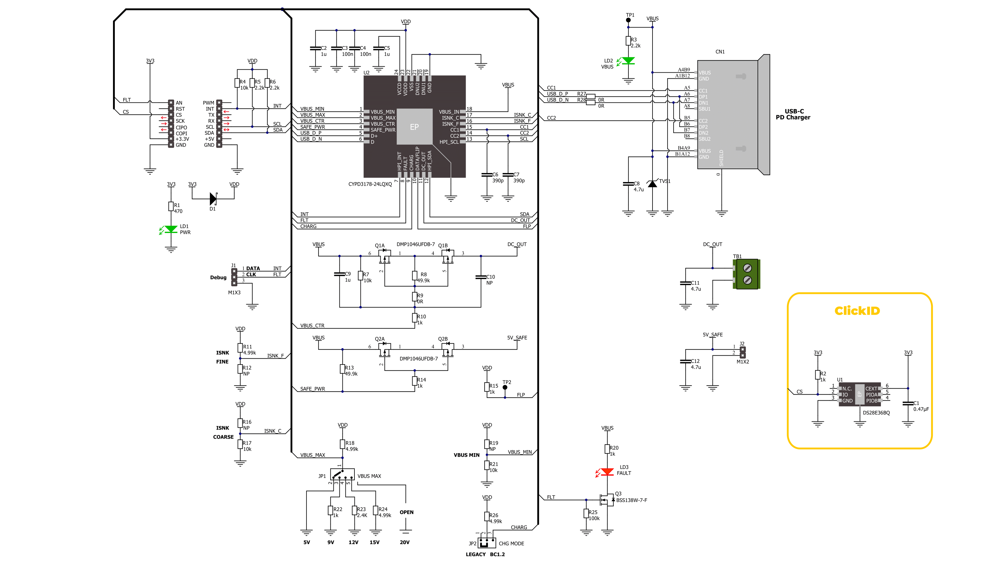
Click board™ Schematic
Step by step
Project assembly

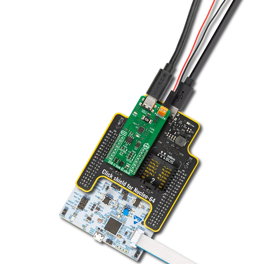
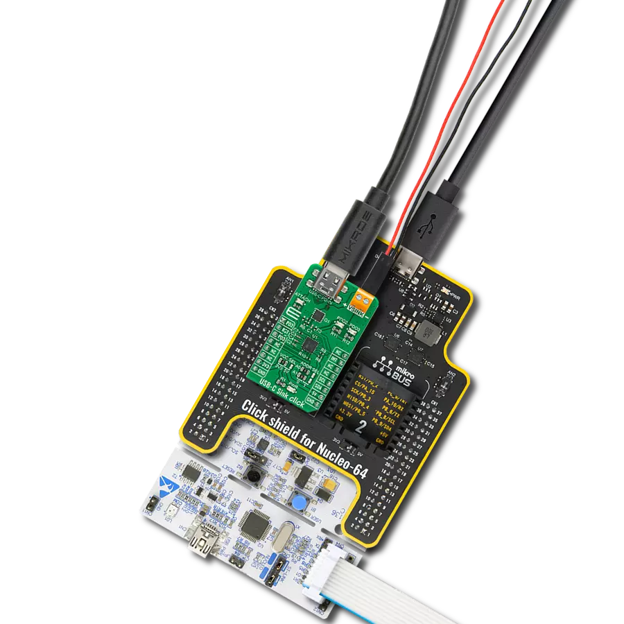
Start by selecting your development board and Click board™. Begin with the EasyAVR v7 as your development board.


Track your results in real time
Application Output
1. Application Output - In Debug mode, the 'Application Output' window enables real-time data monitoring, offering direct insight into execution results. Ensure proper data display by configuring the environment correctly using the provided tutorial.

2. UART Terminal - Use the UART Terminal to monitor data transmission via a USB to UART converter, allowing direct communication between the Click board™ and your development system. Configure the baud rate and other serial settings according to your project's requirements to ensure proper functionality. For step-by-step setup instructions, refer to the provided tutorial.

3. Plot Output - The Plot feature offers a powerful way to visualize real-time sensor data, enabling trend analysis, debugging, and comparison of multiple data points. To set it up correctly, follow the provided tutorial, which includes a step-by-step example of using the Plot feature to display Click board™ readings. To use the Plot feature in your code, use the function: plot(*insert_graph_name*, variable_name);. This is a general format, and it is up to the user to replace 'insert_graph_name' with the actual graph name and 'variable_name' with the parameter to be displayed.

Software Support
Library Description
This library contains API for USB-C Sink 4 Click driver.
Key functions:
usbcsink4_get_type_c_status- This function reads the reports of the status of the Type-C port by using the I2C serial interface.usbcsink4_get_bus_voltage- This function reads the live voltage on the VBUS supply for the specified port using the I2C serial interface.usbcsink4_get_event_status- This function reads the reports of the event status to know what has happened on the Type-C/PD port using the I2C serial interface.
Open Source
Code example
The complete application code and a ready-to-use project are available through the NECTO Studio Package Manager for direct installation in the NECTO Studio. The application code can also be found on the MIKROE GitHub account.
/*!
 * @file main.c
 * @brief USB-C Sink 4 Click example
 *
 * # Description
 * This example demonstrates the use of a USB-C Sink 4 Click board
 * by setting DC power requests and control for Type-C connector-equipped devices (TCD).
 *
 * The demo application is composed of two sections :
 *
 * ## Application Init
 * The initialization of the I2C module and log UART.
 * After driver initialization, the app sets the default configuration.
 *
 * ## Application Task
 * The demo app displays the reports of the Type-C port, active legacy charging mode status,
 * and live voltage measurements on the VBUS supply for the specified port.
 *
 * ## Additional Function
 * - static void usbcsink4_display_type_c_status ( void )
 * - static void usbcsink4_display_chrg_mode ( void )
 * - static void usbcsink4_display_bus_voltage ( void )
 *
 * @author Nenad Filipovic
 *
 */

#include "board.h"
#include "log.h"
#include "usbcsink4.h"

static usbcsink4_t usbcsink4;
static log_t logger;

/**
 * @brief USB-C Sink 4 display Type-C status.
 * @details This function displays the reports of the status of the Type-C port.
 * @return Nothing.
 */
static void usbcsink4_display_type_c_status ( void );

/**
 * @brief USB-C Sink 4 display charging mode status.
 * @details This function displays the reports of the status
 * of the active legacy charging mode.
 * @return Nothing.
 */
static void usbcsink4_display_chrg_mode ( void );

/**
 * @brief USB-C Sink 4 display VBUS voltage.
 * @details This function displays the live voltage
 * on the VBUS supply for the specified port.
 * @return Nothing.
 */
static void usbcsink4_display_bus_voltage ( void );

void application_init ( void )
{
    log_cfg_t log_cfg;  /**< Logger config object. */
    usbcsink4_cfg_t usbcsink4_cfg;  /**< Click config object. */

    /**
     * Logger initialization.
     * Default baud rate: 115200
     * Default log level: LOG_LEVEL_DEBUG
     * @note If USB_UART_RX and USB_UART_TX
     * are defined as HAL_PIN_NC, you will
     * need to define them manually for log to work.
     * See @b LOG_MAP_USB_UART macro definition for detailed explanation.
     */
    LOG_MAP_USB_UART( log_cfg );
    log_init( &logger, &log_cfg );
    log_info( &logger, " Application Init " );

    // Click initialization.
    usbcsink4_cfg_setup( &usbcsink4_cfg );
    USBCSINK4_MAP_MIKROBUS( usbcsink4_cfg, MIKROBUS_1 );
    if ( I2C_MASTER_ERROR == usbcsink4_init( &usbcsink4, &usbcsink4_cfg ) )
    {
        log_error( &logger, " Communication init." );
        for ( ; ; );
    }

    if ( USBCSINK4_ERROR == usbcsink4_default_cfg ( &usbcsink4 ) )
    {
        log_error( &logger, " Default configuration." );
        for ( ; ; );
    }

    log_info( &logger, " Application Task " );
    log_printf( &logger, " ------------------------\r\n" );
    Delay_ms ( 100 );
}

void application_task ( void )
{
    usbcsink4_display_type_c_status( );
    Delay_ms ( 100 );

    usbcsink4_display_chrg_mode( );
    Delay_ms ( 100 );

    usbcsink4_display_bus_voltage( );
    Delay_ms ( 1000 );
}

int main ( void )
{
    /* Do not remove this line or clock might not be set correctly. */
    #ifdef PREINIT_SUPPORTED
    preinit();
    #endif

    application_init( );

    for ( ; ; )
    {
        application_task( );
    }

    return 0;
}

static void usbcsink4_display_type_c_status ( void )
{
    usbcsink4_type_c_status_t type_c_status;
    if ( USBCSINK4_OK == usbcsink4_get_type_c_status( &usbcsink4, &type_c_status ) )
    {
        log_printf( &logger, "  >> Port Partner Connection Status:" );
        if ( USBCSINK4_TYPE_C_ST_PORT_DISCONN == type_c_status.port_par_cxn )
        {
            log_printf( &logger, " Port is not connected to partner.\r\n" );
        }
        else
        {
            log_printf( &logger, " Port is connected to partner.\r\n" );
        }
        log_printf( &logger, " >> CC Polarity:" );
        if ( USBCSINK4_TYPE_C_ST_CC_1 == type_c_status.cc_pol )
        {
            log_printf( &logger, " CC1\r\n" );
        }
        else
        {
            log_printf( &logger, " CC2\r\n" );
        }
        log_printf( &logger, " >> Attached device type:" );
        if ( USBCSINK4_TYPE_C_ST_ATT_NTH == type_c_status.att_dev_type )
        {
            log_printf( &logger, " Nothing attached\r\n" );
        }
        else if ( USBCSINK4_TYPE_C_ST_ATT_SRC == type_c_status.att_dev_type )
        {
            log_printf( &logger, " Source attached\r\n" );
        }
        else if ( USBCSINK4_TYPE_C_ST_ATT_DEBUG == type_c_status.att_dev_type )
        {
            log_printf( &logger, " Debug Accessory attached\r\n" );
        }
        else
        {
            log_printf( &logger, " Unknown\r\n" );
        }
        log_printf( &logger, " >> Type-C Current Level:" );
        if ( USBCSINK4_TYPE_C_ST_CURR_0_9A == type_c_status.curr_lvl )
        {
            log_printf( &logger, " 900mA\r\n" );
        }
        else if ( USBCSINK4_TYPE_C_ST_CURR_1A == type_c_status.curr_lvl )
        {
            log_printf( &logger, " 1.5A\r\n" );
        }
        else if ( USBCSINK4_TYPE_C_ST_CURR_3A == type_c_status.curr_lvl )
        {
            log_printf( &logger, " 3A\r\n" );
        }
        else
        {
            log_printf( &logger, " Unknown\r\n" );
        }
    }
}

static void usbcsink4_display_chrg_mode ( void )
{
    uint8_t chrg_mode = 0;
    if ( USBCSINK4_OK == usbcsink4_get_chrg_mode( &usbcsink4, &chrg_mode ) )
    {
        log_printf( &logger, " >> Charging Mode Status:" );
        if ( USBCSINK4_CHG_MODE_STATUS_NO_LGC == chrg_mode )
        {
            log_printf( &logger, " No legacy charging mode\r\n" );
        }
        if ( USBCSINK4_CHG_MODE_STATUS_BC1_2DCP_CDC == chrg_mode )
        {
            log_printf( &logger, " BC 1.2 DCP/CDP charging\r\n" );
        }
        if ( USBCSINK4_CHG_MODE_STATUS_QC2_1 == chrg_mode )
        {
            log_printf( &logger, " QC2.0 charging\r\n" );
        }
        if ( USBCSINK4_CHG_MODE_STATUS_AFC == chrg_mode )
        {
            log_printf( &logger, " AFC charging\r\n" );
        }
        if ( USBCSINK4_CHG_MODE_STATUS_APPLE == chrg_mode )
        {
            log_printf( &logger, " Apple charging\r\n" );
        }
    }
}

static void usbcsink4_display_bus_voltage ( void )
{
    float vtg = 0;
    if ( USBCSINK4_OK == usbcsink4_get_bus_voltage( &usbcsink4, &vtg ) )
    {
        log_printf( &logger, " >> VBUS Voltage: %.1f V \r\n", vtg );
    }
    log_printf( &logger, " ------------------------\r\n" );
}

// ------------------------------------------------------------------------ END