Elevate your vibrational experience with DRV2605 and ATmega1284
The future of vibration control: ERM and LRA in harmony

Published Sep 09, 2023
Click board™
HAPTIC Click
Dev. board
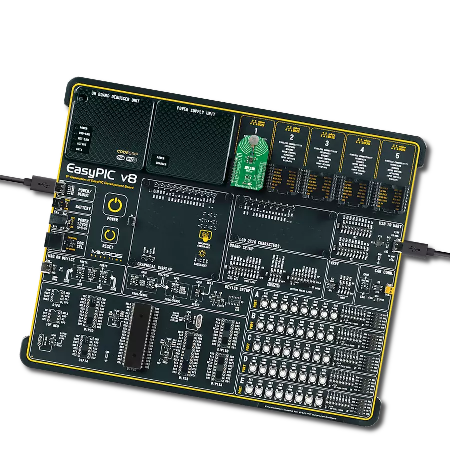
EasyAVR v7
Compiler
NECTO Studio
MCU
ATmega1284
Our solution is engineered to provide precise control over ERM and LRA vibration motors, offering businesses the tools they need to optimize vibrational experiences and meet diverse application needs
A
A
Hardware Overview
How does it work?
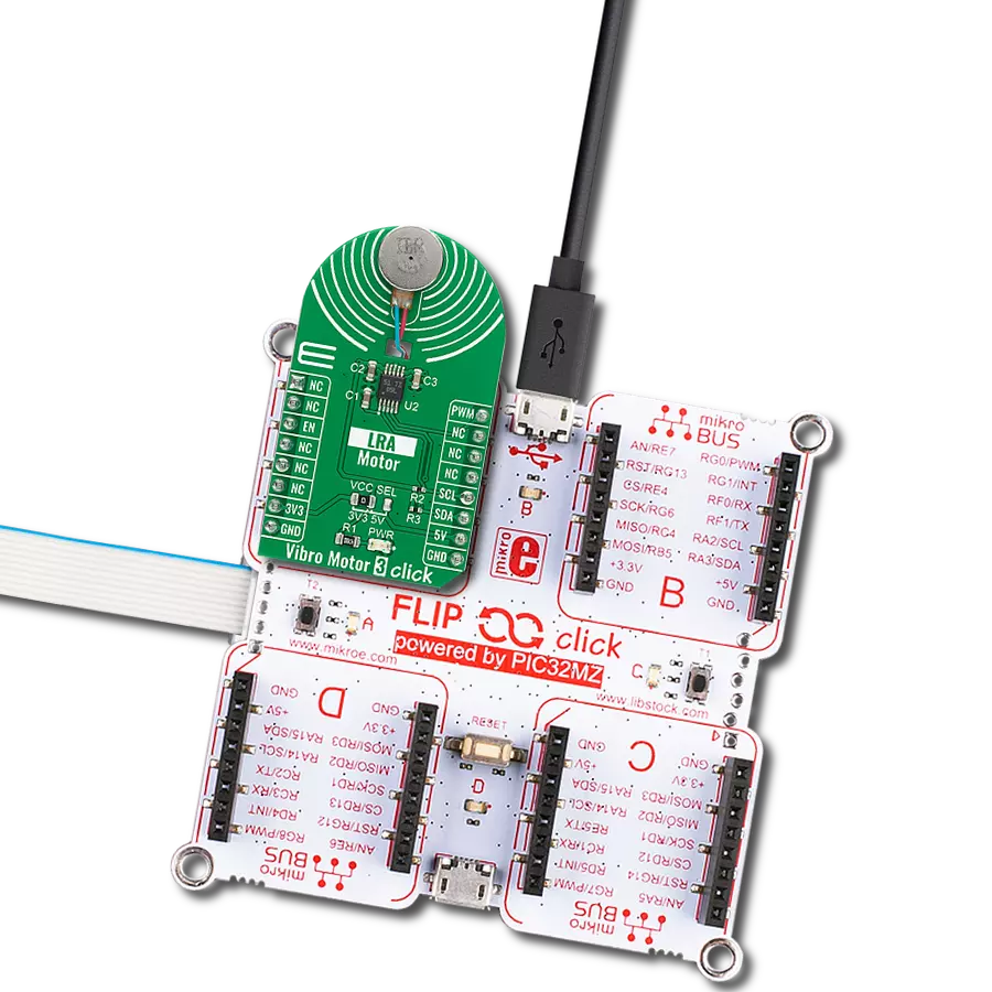
Haptic Click is based on the DRV2605, a haptic driver for ERM and LRA with a built-in library and Smart-Loop architecture from Texas Instruments. It is designed to provide highly flexible haptic control of ERM and LRA actuators over a shared I2C bus, thus relieving the host MCU from generating PWM drive signals and saving costly timer interrupts and hardware pins. Using the ToushSense® 2200 software eliminates the need to design waveforms, too. It includes an extensive effects library and audio vibe features, with a real-time playback mode that allows the host MCU to bypass the library playback engine and play waveforms directly from the host through I2C. The
Smart Loop architecture allows effortless auto resonant drive for LRA and feedback-optimized ERM drive. The audio-to-haptics mode automatically converts an audio input signal to meaningful haptic effects. Haptic Click communicates with the host MCU using a standard I2C 2-Wire interface over the mikroBUS™ socket. The input audio signal to the DRV2605 comes through a 3.5mm audio jack. The channel side (left or right) can be selected over an R4 and R5 pair of jumpers, with R5 populated by default, thus choosing the right channel. The PWM SEL jumper turns off the PWM trigger when unsoldered, thus avoiding potential interference
with audio output. The LRA/ERM screw terminal is used to connect the haptic motor. In addition, this Click board™ features test points to hook up measuring equipment while developing. These test points are connected to the DRV2605 outputs toward LRA/ERM screw terminals. This Click board™ can operate with either 3.3V or 5V logic voltage levels selected via the PWR SEL jumper. This way, both 3.3V and 5V capable MCUs can use the communication lines properly. Also, this Click board™ comes equipped with a library containing easy-to-use functions and an example code that can be used as a reference for further development.

Features overview
Development board
EasyAVR v7 is the seventh generation of AVR development boards specially designed for the needs of rapid development of embedded applications. It supports a wide range of 16-bit AVR microcontrollers from Microchip and has a broad set of unique functions, such as a powerful onboard mikroProg programmer and In-Circuit debugger over USB. The development board is well organized and designed so that the end-user has all the necessary elements in one place, such as switches, buttons, indicators, connectors, and others. With four different connectors for each port, EasyAVR v7 allows you to connect accessory boards, sensors, and custom electronics more
efficiently than ever. Each part of the EasyAVR v7 development board contains the components necessary for the most efficient operation of the same board. An integrated mikroProg, a fast USB 2.0 programmer with mikroICD hardware In-Circuit Debugger, offers many valuable programming/debugging options and seamless integration with the Mikroe software environment. Besides it also includes a clean and regulated power supply block for the development board. It can use a wide range of external power sources, including an external 12V power supply, 7-12V AC or 9-15V DC via DC connector/screw terminals, and a power source via the USB Type-B (USB-B)
connector. Communication options such as USB-UART and RS-232 are also included, alongside the well-established mikroBUS™ standard, three display options (7-segment, graphical, and character-based LCD), and several different DIP sockets which cover a wide range of 16-bit AVR MCUs. EasyAVR v7 is an integral part of the Mikroe ecosystem for rapid development. Natively supported by Mikroe software tools, it covers many aspects of prototyping and development thanks to a considerable number of different Click boards™ (over a thousand boards), the number of which is growing every day.

Microcontroller Overview
MCU Card / MCU

Architecture
AVR
MCU Memory (KB)
128
Silicon Vendor
Microchip
Pin count
40
RAM (Bytes)
16384
You complete me!
Accessories
Vibration ERM Motor 9K RPM 3V (VC1026B002F - old MPN C1026B002F) represents a compact-size Eccentric Rotating Mass (ERM) motor designed by Vybronics. This type of motor contains a small eccentric weight on its rotor, so while rotating, it also produces a vibration effect often used for haptic feedback on many small handheld devices. Due to its circular shape with a diameter of 10mm, the VC1026B002F is often referred to as a coin motor. The main characteristics of this vibration motor are its supply voltage, in this case, 3VDC, maximum rated current of 85mA, and the rated speed of 9000RPM, which produces the highest G force/vibration energy of 0.80GRMS. It can also be used with self-adhesive tape to mount it on your PCB or the inner wall of your product's housing.

Used MCU Pins
mikroBUS™ mapper
Take a closer look
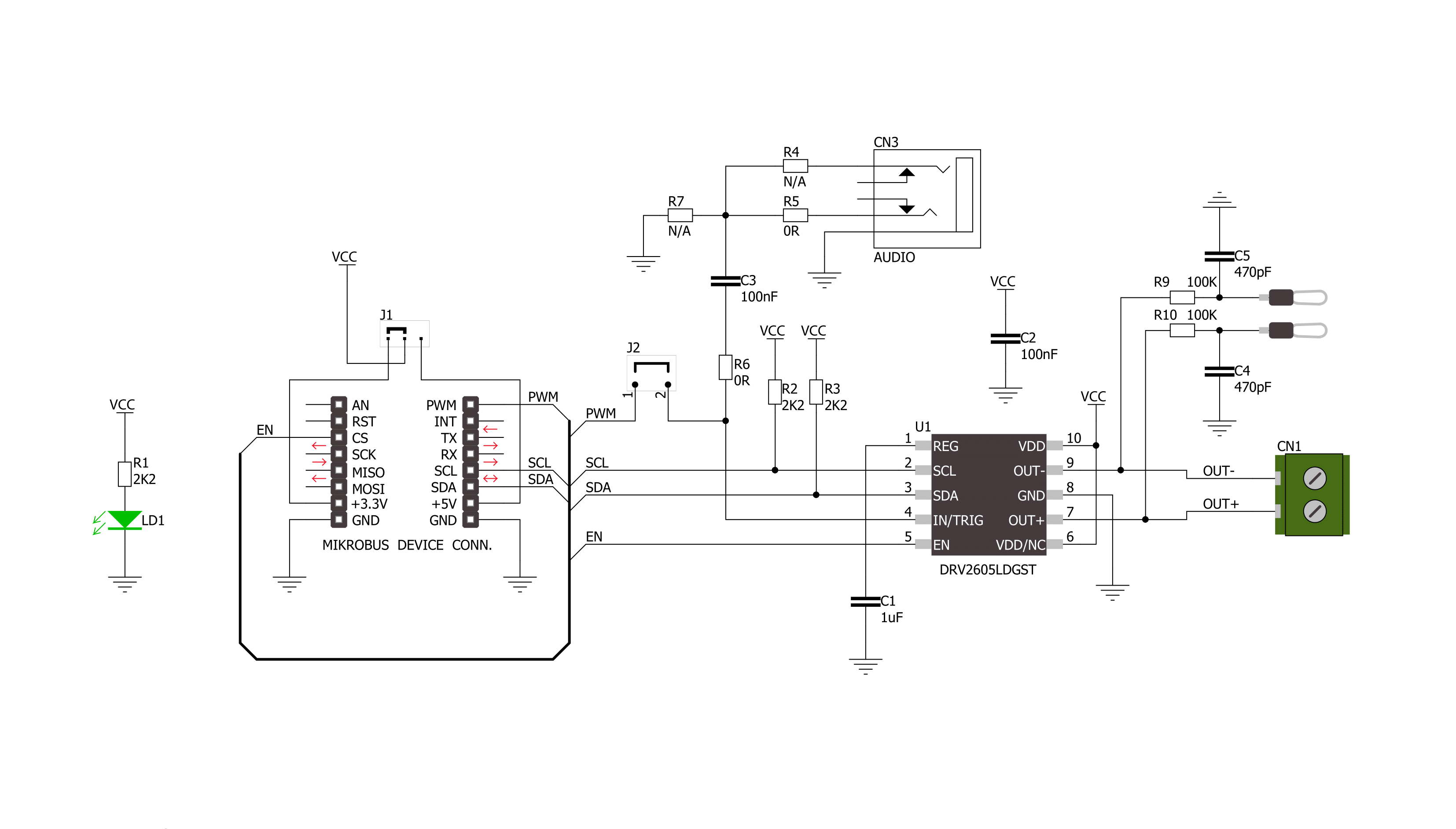
Click board™ Schematic
Step by step
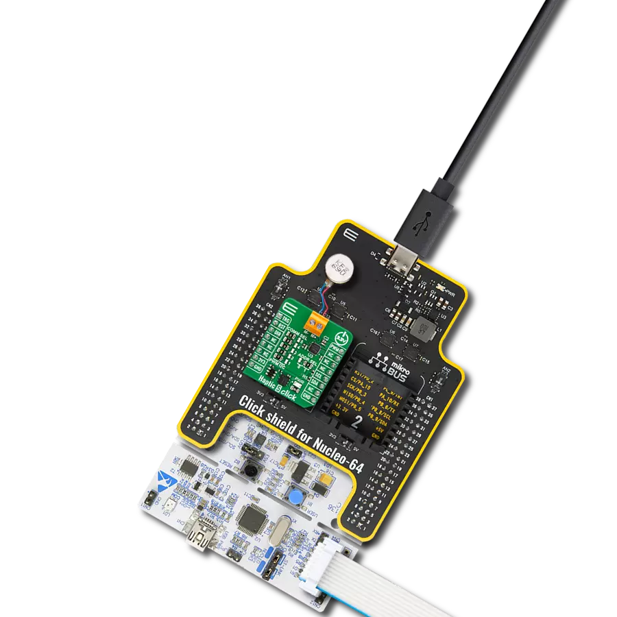
Project assembly

Start by selecting your development board and Click board™. Begin with the EasyAVR v7 as your development board.


Software Support
Library Description
This library contains API for HAPTIC Click driver.
Key functions:
haptic_enable- Enable the device functionhaptic_disable- Disable the device functionhaptic_set_mode- Sets the Haptic click to desired mode function.
Open Source
Code example
The complete application code and a ready-to-use project are available through the NECTO Studio Package Manager for direct installation in the NECTO Studio. The application code can also be found on the MIKROE GitHub account.
/*!
 * \file
 * \brief Haptic Click example
 *
 * # Description
 * This application generate vibrations from the lower frequency range of the audio input.
 *
 * The demo application is composed of two sections :
 *
 * ## Application Init
 * Configures the Click board in Audio-to-Vibe mode.
 *
 * ## Application Task
 * An infinite loop.
 *
 * \author MikroE Team
 *
 */
// ------------------------------------------------------------------- INCLUDES

#include "board.h"
#include "log.h"
#include "haptic.h"

// ------------------------------------------------------------------ VARIABLES

static haptic_t haptic;
static log_t logger;

void application_init ( void )
{
    log_cfg_t log_cfg;
    haptic_cfg_t cfg;

    /**
     * Logger initialization.
     * Default baud rate: 115200
     * Default log level: LOG_LEVEL_DEBUG
     * @note If USB_UART_RX and USB_UART_TX
     * are defined as HAL_PIN_NC, you will
     * need to define them manually for log to work.
     * See @b LOG_MAP_USB_UART macro definition for detailed explanation.
     */
    LOG_MAP_USB_UART( log_cfg );
    log_init( &logger, &log_cfg );
    log_info( &logger, "---- Application Init ----" );

    //  Click initialization.

    haptic_cfg_setup( &cfg );
    HAPTIC_MAP_MIKROBUS( cfg, MIKROBUS_1 );
    haptic_init( &haptic, &cfg );

    log_printf( &logger, " Configuring the Click board...\r\n" );
    log_printf( &logger, "----------------------- \r\n" );

    haptic_enable( &haptic );
    haptic_set_mode( &haptic, HAPTIC_MODE_AUTOCAL );
    haptic_start_motor( &haptic );
    Delay_ms ( 500 );

    haptic_set_mode( &haptic, HAPTIC_MODE_AUDIOVIBE );
    haptic_enable_ac_coulping( &haptic );
    haptic_set_input_to_analog( &haptic );

    log_printf( &logger, " The Click board is configured in Audio-to-Vibe mode...\r\n" );
}

void application_task ( void )
{
    // Nothing to do here...
}

int main ( void )
{
    /* Do not remove this line or clock might not be set correctly. */
    #ifdef PREINIT_SUPPORTED
    preinit();
    #endif

    application_init( );

    for ( ; ; )
    {
        application_task( );
    }

    return 0;
}
// ------------------------------------------------------------------------ END
Additional Support
Resources
Category:Haptic