Enable users to tailor vibration patterns to their preferences using G0832022D and STM32F302VC
Shake up your world with control
Published Jul 22, 2025
Click board™
Vibro Motor 3 Click
Dev. board
CLICKER 4 for STM32F302VCT6
Compiler
NECTO Studio
MCU
STM32F302VC
Fine-tune your device notifications with precision, ensuring that users receive alerts in a more discreet and personalized manner
A
A
Hardware Overview
How does it work?
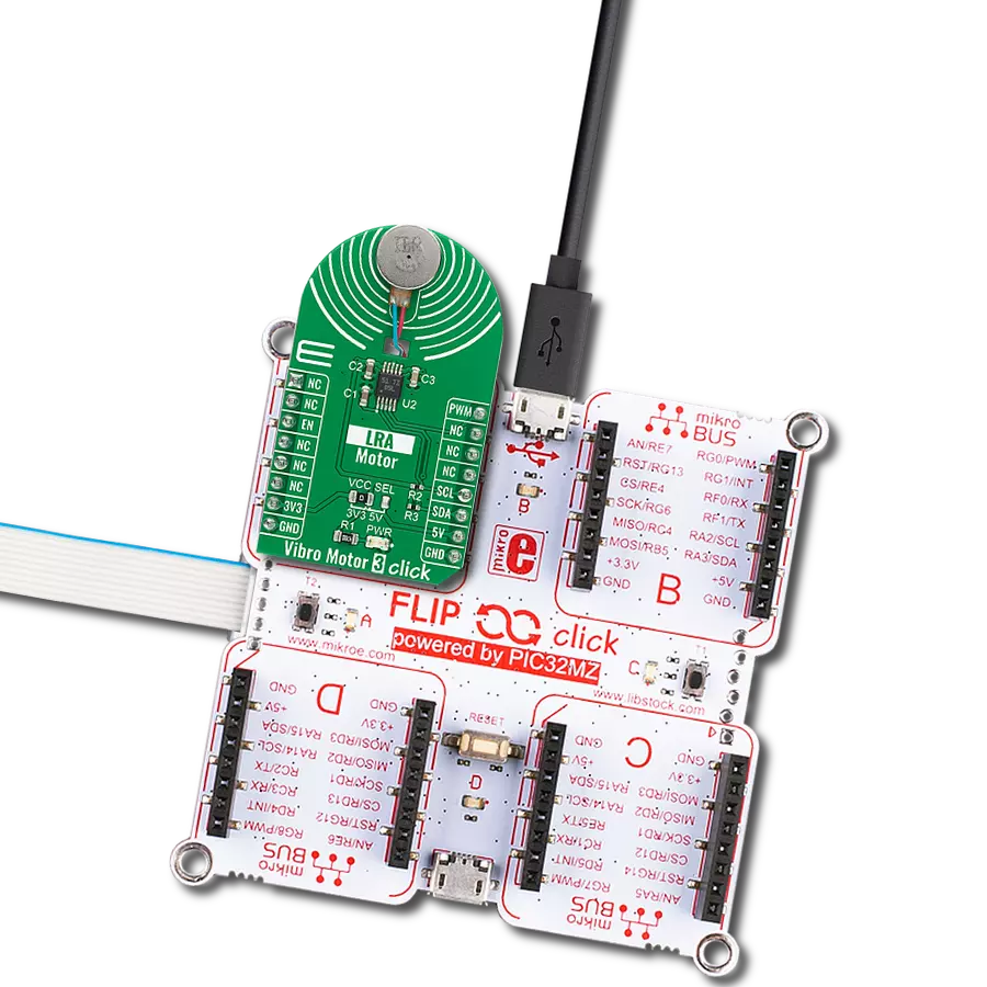
Vibro Motor 3 Click is based on the G0832022D, a coin-sized linear resonant actuator that generates vibration/haptic feedback in the Z plane, perpendicular to the motor's surface from Jinlong Machinery & Electronics, Inc. The G0832022D draws only 19mA at 0.6V while producing a G force of 0.55 GRMS and makes an excellent choice for applications requiring crisp haptic feedback and low power consumption. For haptic feedback applications, fast rise and fall times are critical for achieving the optimal user experience. Driven by the DRV2605, a flexible Haptic/Vibra driver from Texas Instruments, this Click board™ is designed to provide highly flexible haptic control over a standard I2C 2-Wire interface with a maximum clock frequency of 400kHz. It possesses an enabling function, routed on the CS pin
of the mikroBUS™ socket labeled as the EN, and comes up with an extensive integrated library of over 100 licensed effects that eliminates the need to design haptics waveforms. It also contains a smart-loop architecture, which allows effortless auto resonant drive for LRA motor drive. This feedback provides automatic overdrive and braking, which creates a simplified input waveform paradigm, reliable motor control, and consistent motor performance. The DRV2605 can also operate in the PWM Mode and accept the PWM signal from the PWM pin of the mikroBUS™ socket. In this mode, the DRV2605 device drives the actuator continuously until the user sets the DRV2605 to a Standby Mode or enters another interface mode. In PWM Mode, the vibration strength is controlled by the duty cycle, and
for the LRA motor, the DRV2605 automatically tracks the resonance frequency unless the LRA_OPEN_LOOP bit in register 0x1D is set. If the LRA_OPEN_LOOP bit is set, then the LRA motor is driven according to the frequency of the PWM input signal. More information about the operating modes of the DRV2605 can be found in the attached datasheet. This Click board™ can operate with either 3.3V or 5V logic voltage levels selected via the VCC SEL jumper. This way, both 3.3V and 5V capable MCUs can use the communication lines properly. Also, this Click board™ comes equipped with a library containing easy-to-use functions and an example code that can be used as a reference for further development.


Features overview
Development board
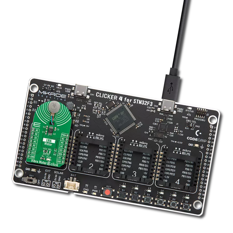
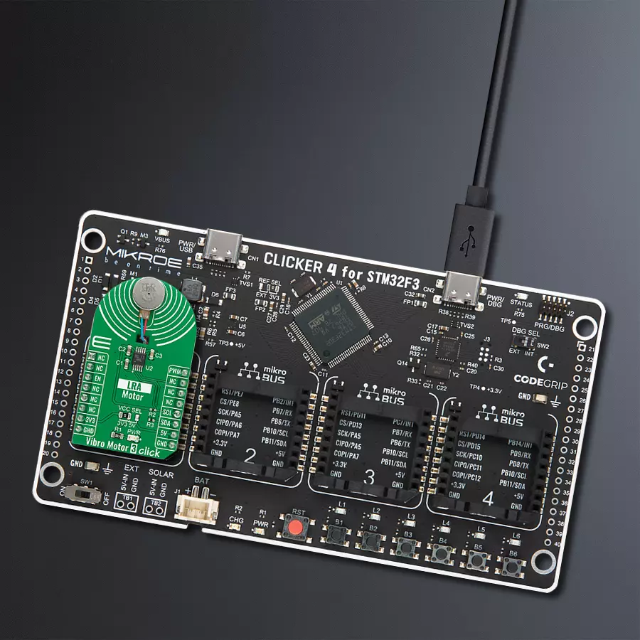
Clicker 4 for STM32F3 is a compact development board designed as a complete solution, you can use it to quickly build your own gadgets with unique functionalities. Featuring a STM32F302VCT6, four mikroBUS™ sockets for Click boards™ connectivity, power managment, and more, it represents a perfect solution for the rapid development of many different types of applications. At its core, there is a STM32F302VCT6 MCU, a powerful microcontroller by STMicroelectronics, based on the high-
performance Arm® Cortex®-M4 32-bit processor core operating at up to 168 MHz frequency. It provides sufficient processing power for the most demanding tasks, allowing Clicker 4 to adapt to any specific application requirements. Besides two 1x20 pin headers, four improved mikroBUS™ sockets represent the most distinctive connectivity feature, allowing access to a huge base of Click boards™, growing on a daily basis. Each section of Clicker 4 is clearly marked, offering an intuitive and clean interface. This makes working with the development
board much simpler and thus, faster. The usability of Clicker 4 doesn’t end with its ability to accelerate the prototyping and application development stages: it is designed as a complete solution which can be implemented directly into any project, with no additional hardware modifications required. Four mounting holes [4.2mm/0.165”] at all four corners allow simple installation by using mounting screws. For most applications, a nice stylish casing is all that is needed to turn the Clicker 4 development board into a fully functional, custom design.

Microcontroller Overview
MCU Card / MCU

Architecture
ARM Cortex-M4
MCU Memory (KB)
256
Silicon Vendor
STMicroelectronics
Pin count
100
RAM (Bytes)
40960
Used MCU Pins
mikroBUS™ mapper
Take a closer look
Click board™ Schematic

Step by step
Project assembly

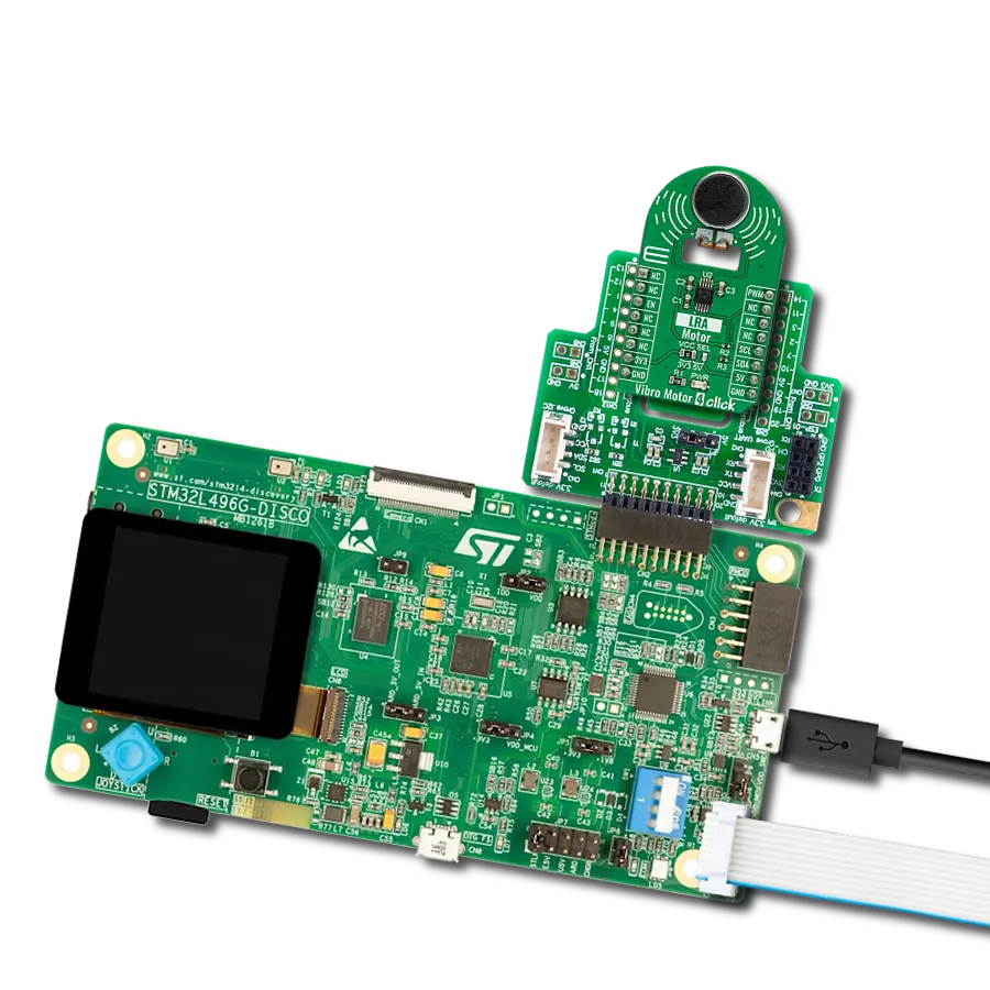
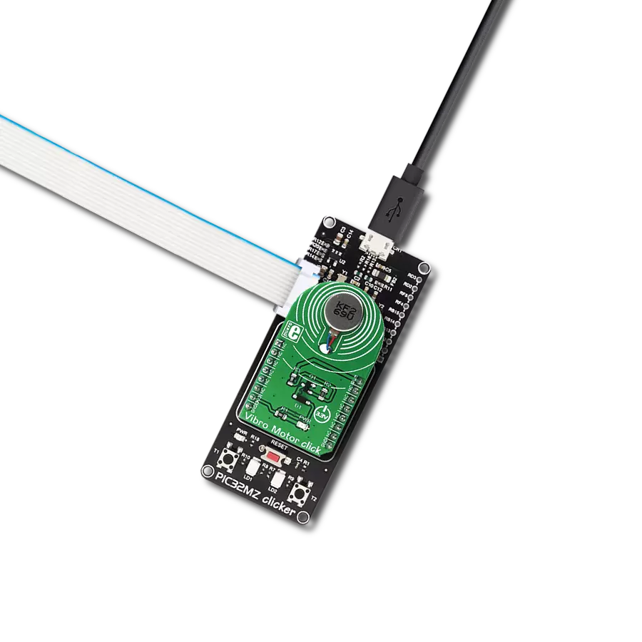
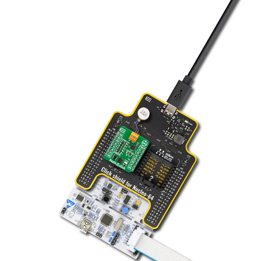
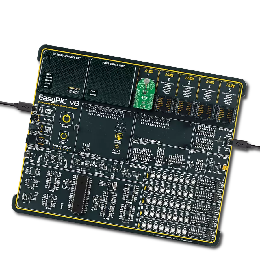
Start by selecting your development board and Click board™. Begin with the CLICKER 4 for STM32F302VCT6 as your development board.


Track your results in real time
Application Output
1. Application Output - In Debug mode, the 'Application Output' window enables real-time data monitoring, offering direct insight into execution results. Ensure proper data display by configuring the environment correctly using the provided tutorial.

2. UART Terminal - Use the UART Terminal to monitor data transmission via a USB to UART converter, allowing direct communication between the Click board™ and your development system. Configure the baud rate and other serial settings according to your project's requirements to ensure proper functionality. For step-by-step setup instructions, refer to the provided tutorial.

3. Plot Output - The Plot feature offers a powerful way to visualize real-time sensor data, enabling trend analysis, debugging, and comparison of multiple data points. To set it up correctly, follow the provided tutorial, which includes a step-by-step example of using the Plot feature to display Click board™ readings. To use the Plot feature in your code, use the function: plot(*insert_graph_name*, variable_name);. This is a general format, and it is up to the user to replace 'insert_graph_name' with the actual graph name and 'variable_name' with the parameter to be displayed.

Software Support
Library Description
This library contains API for Vibro Motor 3 Click driver.
Key functions:
vibromotor3_set_duty_cycle- Vibro Motor 3 sets PWM duty cyclevibromotor3_enable- Enable the device functionvibromotor3_write_byte- Generic write the byte of data function
Open Source
Code example
The complete application code and a ready-to-use project are available through the NECTO Studio Package Manager for direct installation in the NECTO Studio. The application code can also be found on the MIKROE GitHub account.
/*!
 * @file main.c
 * @brief VibroMotor3 Click example
 *
 * # Description
 * This example shows the capabilities of the Vibro Motor 3 Click board
 *
 * The demo application is composed of two sections :
 *
 * ## Application Init
 * Initalizes I2C driver, PWM driver and configures Vibro Motor 3 Click board.
 *
 * ## Application Task
 * Changing duty cycle applied in order to get different vibrations.
 *
 * @author Stefan Ilic
 *
 */

#include "board.h"
#include "log.h"
#include "vibromotor3.h"

static vibromotor3_t vibromotor3;
static log_t logger;

static float pwm_max_duty = 1;
static float pwm_duty_cycle = 0;


void application_init ( void ) {
    log_cfg_t log_cfg;  /**< Logger config object. */
    vibromotor3_cfg_t vibromotor3_cfg;  /**< Click config object. */

    /**
     * Logger initialization.
     * Default baud rate: 115200
     * Default log level: LOG_LEVEL_DEBUG
     * @note If USB_UART_RX and USB_UART_TX
     * are defined as HAL_PIN_NC, you will
     * need to define them manually for log to work.
     * See @b LOG_MAP_USB_UART macro definition for detailed explanation.
     */
    LOG_MAP_USB_UART( log_cfg );
    log_init( &logger, &log_cfg );
    log_info( &logger, " Application Init " );

    // Click initialization.
    vibromotor3_cfg_setup( &vibromotor3_cfg );
    VIBROMOTOR3_MAP_MIKROBUS( vibromotor3_cfg, MIKROBUS_1 );
    err_t init_flag = vibromotor3_init( &vibromotor3, &vibromotor3_cfg );
    if ( I2C_MASTER_ERROR == init_flag || PWM_ERROR == init_flag ) {
        log_error( &logger, " Application Init Error. " );
        log_info( &logger, " Please, run program again... " );

        for ( ; ; );
    }
    vibromotor3_enable( &vibromotor3, VIBROMOTOR3_PROPERTY_ENABLE );
    Delay_ms ( 100 );

    vibromotor3_soft_rst( &vibromotor3 );
    Delay_ms ( 100 );

    vibromotor3_default_cfg( &vibromotor3 );
    Delay_ms ( 100 );

    vibromotor3_set_duty_cycle( &vibromotor3, 0.0 );
    vibromotor3_pwm_start( &vibromotor3 );
    Delay_ms ( 100 );

    log_info( &logger, " Application Task " );
    Delay_ms ( 100 );
}

void application_task ( void ) {
    static int8_t duty_cnt = 1;
    static int8_t duty_inc = 1;
    float duty = duty_cnt / 10.0;

    vibromotor3_set_duty_cycle ( &vibromotor3, duty );
    log_printf( &logger, "> Duty: %d%%\r\n", ( uint16_t )( duty_cnt * 10 ) );

    Delay_ms ( 500 );

    if ( 10 == duty_cnt ) {
        duty_inc = -1;
    } else if ( 0 == duty_cnt ) {
        duty_inc = 1;
    }
    duty_cnt += duty_inc;
}

int main ( void )
{
    /* Do not remove this line or clock might not be set correctly. */
    #ifdef PREINIT_SUPPORTED
    preinit();
    #endif

    application_init( );

    for ( ; ; )
    {
        application_task( );
    }

    return 0;
}

// ------------------------------------------------------------------------ END
Additional Support
Resources
Category:Haptic