Achieve enhanced motor control and efficiency with DRV8871 and ATmega644
Dominate with swift motor drive

Published May 31, 2023
Click board™
DC Motor 9 Click
Dev. board
EasyAVR v7
Compiler
NECTO Studio
MCU
ATmega644
Monitor the current consumption of your motor at all times. Upgrade your engineering toolkit, and embrace the possibilities of brushed motor control.
A
A
Hardware Overview
How does it work?
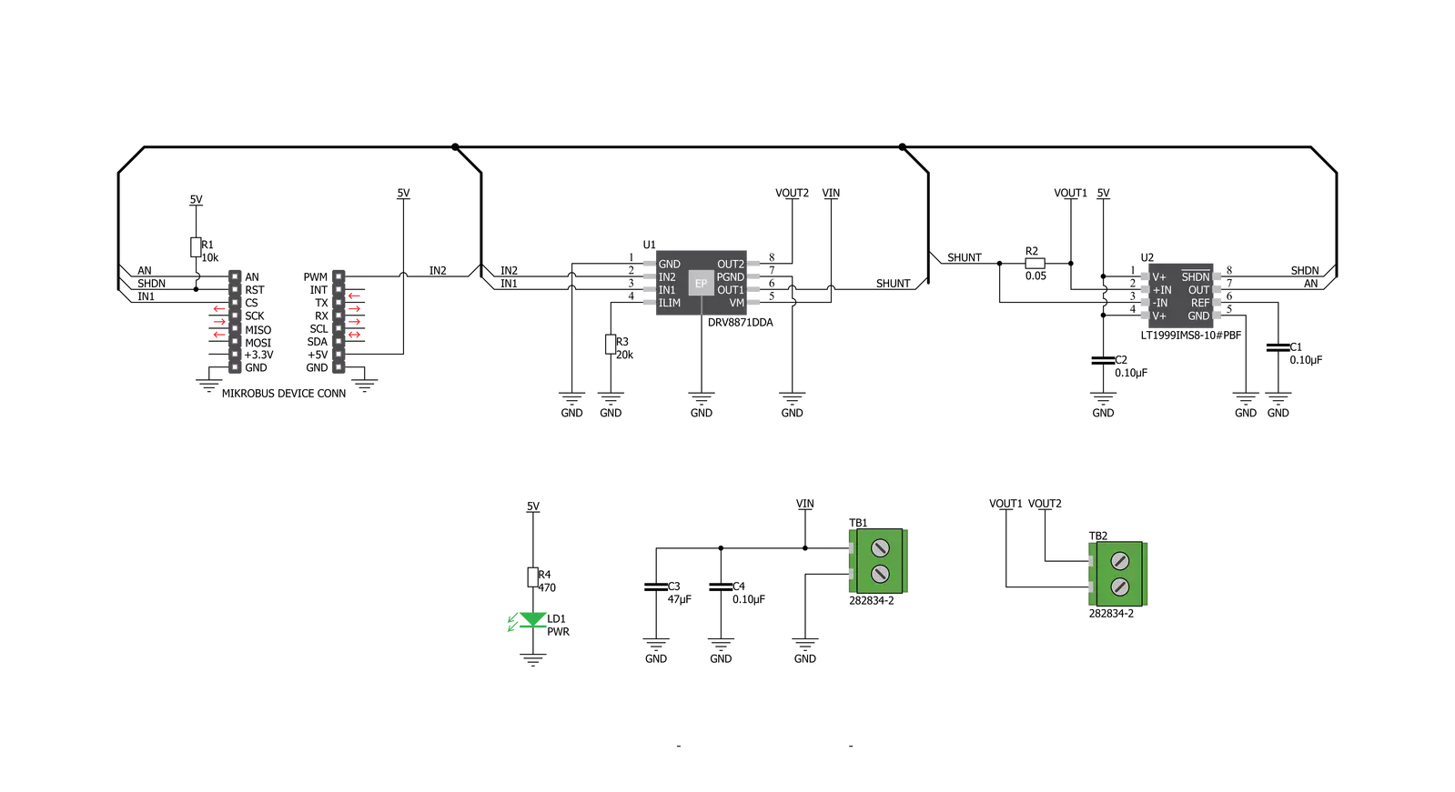
DC Motor 9 Click is based on the DR8871, a brushed DC motor driver with internal current sensing, by Texas Instruments. This IC is an integrated H-Bridge driver with a current regulation circuit limiting the current through the connected load with a single resistor. Unlike many other solutions, no external sensing resistors are required. A low ON resistance through the H-Bridge reduces the overall power dissipation, while an advanced control circuit injects dead-time intervals whenever the outputs change their state, preventing current shoot-throughs. The DRV8871 integrates protection features, including undervoltage, overcurrent, and overtemperature protection. Each of these events will cause the H-Bridge MOSFETs to be disabled. After removing a fault condition, the device will continue its operation. Two methods can be used to control the motor: the first consists of applying a constant logic level to IN1 and IN2 inputs. While one of the inputs is held at a HIGH logic level, the other should be held at a LOW logic level. The direction of the motor rotation depends on which input is at the
HIGH logic level. The second method involves holding one pin to the LOW level while applying a PWM signal to the other. Changing the PWM frequency makes it possible to control the speed of the motor, while the direction of the motor rotation is determined by the pin the PWM signal is applied to. Both pins to HIGH will set all the MOSFETs in HIGH-Z mode (coast), allowing the backEMF-generated current to return to the source through the MOSFET body diodes. If both IN1 and IN2 pins are set to the LOW logic level, the connected motor is in a braking state. When the PWM signal is applied, the motor will be switched between the braking and rotating modes, causing it to slow down, depending on the pulse width of the applied PWM signal. The frequency of the PWM signal can range between 0 and 200 kHz, with the limitation that the PWM pulses must stay above 800ns for proper detection. Current through the connected load is internally limited to a maximum of 3.6A. A higher current will cause the overcurrent protection to be activated. The peak current through the motor is
limited to about 3.2A, ensuring reliable spin-up while preventing the overcurrent protection from being activated, even if a large load torque is applied. Although there is a low resistance across the H-Bridge, the current should be monitored to prevent excessive heating in situations where the load is reasonably high. Therefore, an additional IC is added, allowing the current to be monitored. The Click board™ uses the LT1999, a bidirectional current sense amplifier from Analog Devices (Linear Technology division). It is used to amplify voltage drop across the shunt resistor so that it can be accurately sampled. The output of the LT1999 IC is routed to the AN pin of the mikroBUS™, allowing the host MCU to sense the current using its integrated ADC module. This Click board™ can only be operated with a 5V logic voltage level. The board must perform appropriate logic voltage level conversion before using MCUs with different logic levels. However, the Click board™ comes equipped with a library containing functions and an example code that can be used as a reference for further development.

Features overview
Development board
EasyAVR v7 is the seventh generation of AVR development boards specially designed for the needs of rapid development of embedded applications. It supports a wide range of 16-bit AVR microcontrollers from Microchip and has a broad set of unique functions, such as a powerful onboard mikroProg programmer and In-Circuit debugger over USB. The development board is well organized and designed so that the end-user has all the necessary elements in one place, such as switches, buttons, indicators, connectors, and others. With four different connectors for each port, EasyAVR v7 allows you to connect accessory boards, sensors, and custom electronics more
efficiently than ever. Each part of the EasyAVR v7 development board contains the components necessary for the most efficient operation of the same board. An integrated mikroProg, a fast USB 2.0 programmer with mikroICD hardware In-Circuit Debugger, offers many valuable programming/debugging options and seamless integration with the Mikroe software environment. Besides it also includes a clean and regulated power supply block for the development board. It can use a wide range of external power sources, including an external 12V power supply, 7-12V AC or 9-15V DC via DC connector/screw terminals, and a power source via the USB Type-B (USB-B)
connector. Communication options such as USB-UART and RS-232 are also included, alongside the well-established mikroBUS™ standard, three display options (7-segment, graphical, and character-based LCD), and several different DIP sockets which cover a wide range of 16-bit AVR MCUs. EasyAVR v7 is an integral part of the Mikroe ecosystem for rapid development. Natively supported by Mikroe software tools, it covers many aspects of prototyping and development thanks to a considerable number of different Click boards™ (over a thousand boards), the number of which is growing every day.

Microcontroller Overview
MCU Card / MCU

Architecture
AVR
MCU Memory (KB)
64
Silicon Vendor
Microchip
Pin count
40
RAM (Bytes)
4096
You complete me!
Accessories
DC Gear Motor - 430RPM (3-6V) represents an all-in-one combination of a motor and gearbox, where the addition of gear leads to a reduction of motor speed while increasing the torque output. This gear motor has a spur gearbox, making it a highly reliable solution for applications with lower torque and speed requirements. The most critical parameters for gear motors are speed, torque, and efficiency, which are, in this case, 520RPM with no load and 430RPM at maximum efficiency, alongside a current of 60mA and a torque of 50g.cm. Rated for a 3-6V operational voltage range and clockwise/counterclockwise rotation direction, this motor represents an excellent solution for many functions initially performed by brushed DC motors in robotics, medical equipment, electric door locks, and much more.

Used MCU Pins
mikroBUS™ mapper
Take a closer look
Click board™ Schematic
Step by step
Project assembly

Start by selecting your development board and Click board™. Begin with the EasyAVR v7 as your development board.


Track your results in real time
Application Output
1. Application Output - In Debug mode, the 'Application Output' window enables real-time data monitoring, offering direct insight into execution results. Ensure proper data display by configuring the environment correctly using the provided tutorial.

2. UART Terminal - Use the UART Terminal to monitor data transmission via a USB to UART converter, allowing direct communication between the Click board™ and your development system. Configure the baud rate and other serial settings according to your project's requirements to ensure proper functionality. For step-by-step setup instructions, refer to the provided tutorial.

3. Plot Output - The Plot feature offers a powerful way to visualize real-time sensor data, enabling trend analysis, debugging, and comparison of multiple data points. To set it up correctly, follow the provided tutorial, which includes a step-by-step example of using the Plot feature to display Click board™ readings. To use the Plot feature in your code, use the function: plot(*insert_graph_name*, variable_name);. This is a general format, and it is up to the user to replace 'insert_graph_name' with the actual graph name and 'variable_name' with the parameter to be displayed.

Software Support
Library Description
This library contains API for DC Motor 9 Click driver.
Key functions:
dcmotor9_generic_read- This function read ADC data.dcmotor9_pwm_start- This function starts PWM module.dcmotor9_set_duty_cycle- This function sets the PWM duty cycle.
Open Source
Code example
The complete application code and a ready-to-use project are available through the NECTO Studio Package Manager for direct installation in the NECTO Studio. The application code can also be found on the MIKROE GitHub account.
/*!
 * @file main.c
 * @brief DC Motor 9 Click Example
 *
 * # Description
 * DC Motor 9 Click is a brushed DC motor driver with the current limiting and
 * current sensing. It can be operated by two logic signals, allowing to drive
 * the connected motor in two different ways:
 * it can use fixed logic levels for the direction control,
 * or it can be controlled by a PWM signal, offering an additional speed control
 * option.
 *
 * The demo application is composed of two sections :
 *
 * ## Application Init
 * Initializes GPIO, PWM and logger and enables the Click board.
 *
 * ## Application Task
 * This is a example which demonstrates the use of DC Motor 9 Click board.
 * DC Motor 9 Click controls DC Motor speed via PWM interface.
 * It shows moving in the both directions from slow to fast speed
 * and from fast to slow speed.
 * Results are being sent to the Usart Terminal where you can track their changes.
 *
 * @author Nikola Peric
 *
 */
// ------------------------------------------------------------------- INCLUDES

#include "board.h"
#include "log.h"
#include "dcmotor9.h"

// ------------------------------------------------------------------ VARIABLES

static dcmotor9_t dcmotor9;
static log_t logger;

// ------------------------------------------------------ APPLICATION FUNCTIONS

void application_init ( void )
{
    log_cfg_t log_cfg;
    dcmotor9_cfg_t dcmotor9_cfg;

    /**
     * Logger initialization.
     * Default baud rate: 115200
     * Default log level: LOG_LEVEL_DEBUG
     * @note If USB_UART_RX and USB_UART_TX
     * are defined as HAL_PIN_NC, you will
     * need to define them manually for log to work.
     * See @b LOG_MAP_USB_UART macro definition for detailed explanation.
     */
    LOG_MAP_USB_UART( log_cfg );
    log_init( &logger, &log_cfg );
    log_info( &logger, "---- Application Init ----" );

    //  Click initialization.

    dcmotor9_cfg_setup( &dcmotor9_cfg );
    DCMOTOR9_MAP_MIKROBUS( dcmotor9_cfg, MIKROBUS_1 );
    if ( dcmotor9_init( &dcmotor9, &dcmotor9_cfg ) == PWM_ERROR )
    {
        log_info( &logger, "---- Application Init Error ----" );
        log_info( &logger, "---- Please, run program again ----" );

        for ( ; ; );
    }

    dcmotor9_set_duty_cycle ( &dcmotor9, DCMOTOR9_PWM_DUTY_PERCENT_0 );

    dcmotor9_enable( &dcmotor9 );
    dcmotor9_pwm_start( &dcmotor9 );
    log_info( &logger, "---- Application Task ----" );
    Delay_ms ( 1000 );
}

void application_task ( void )
{
    static float duty;
    static uint8_t n_cnt;

    dcmotor9_clockwise ( &dcmotor9 );
    log_printf( &logger, "> CLOCKWISE <\r\n" );
    dcmotor9_enable ( &dcmotor9 );

    for ( n_cnt = 10; n_cnt > 0; n_cnt--  )
    {
        duty = ( float ) n_cnt ;
        duty /= 10;
        dcmotor9_set_duty_cycle( &dcmotor9, duty );
        Delay_ms ( 500 );
    }
    for ( n_cnt = 1; n_cnt <= 10; n_cnt++ )
    {
        duty = ( float ) n_cnt ;
        duty /= 10;
        dcmotor9_set_duty_cycle( &dcmotor9,  duty );
        Delay_ms ( 500 );
    }

    log_printf( &logger, "* Pull break *\r\n" );
    dcmotor9_short_brake( &dcmotor9 );
    Delay_ms ( 1000 );

    dcmotor9_counter_clockwise ( &dcmotor9 );
    log_printf( &logger, "> COUNTER CLOCKWISE <\r\n" );

    for ( n_cnt = 1; n_cnt <= 10; n_cnt++  )
    {
        duty = ( float ) n_cnt ;
        duty /= 10;
        dcmotor9_set_duty_cycle( &dcmotor9, duty );
        Delay_ms ( 500 );
    }
    for ( n_cnt = 10; n_cnt > 0; n_cnt-- )
    {
        duty = ( float ) n_cnt ;
        duty /= 10;
        dcmotor9_set_duty_cycle( &dcmotor9,  duty );
        Delay_ms ( 500 );
    }

}

int main ( void )
{
    /* Do not remove this line or clock might not be set correctly. */
    #ifdef PREINIT_SUPPORTED
    preinit();
    #endif

    application_init( );

    for ( ; ; )
    {
        application_task( );
    }

    return 0;
}

// ------------------------------------------------------------------------ END


