Maximize your data transmission capabilities with EMB-LR1276S and ATmega644P
Reaching new horizons with 868MHz long-range transceivers

Published Nov 09, 2023
Click board™
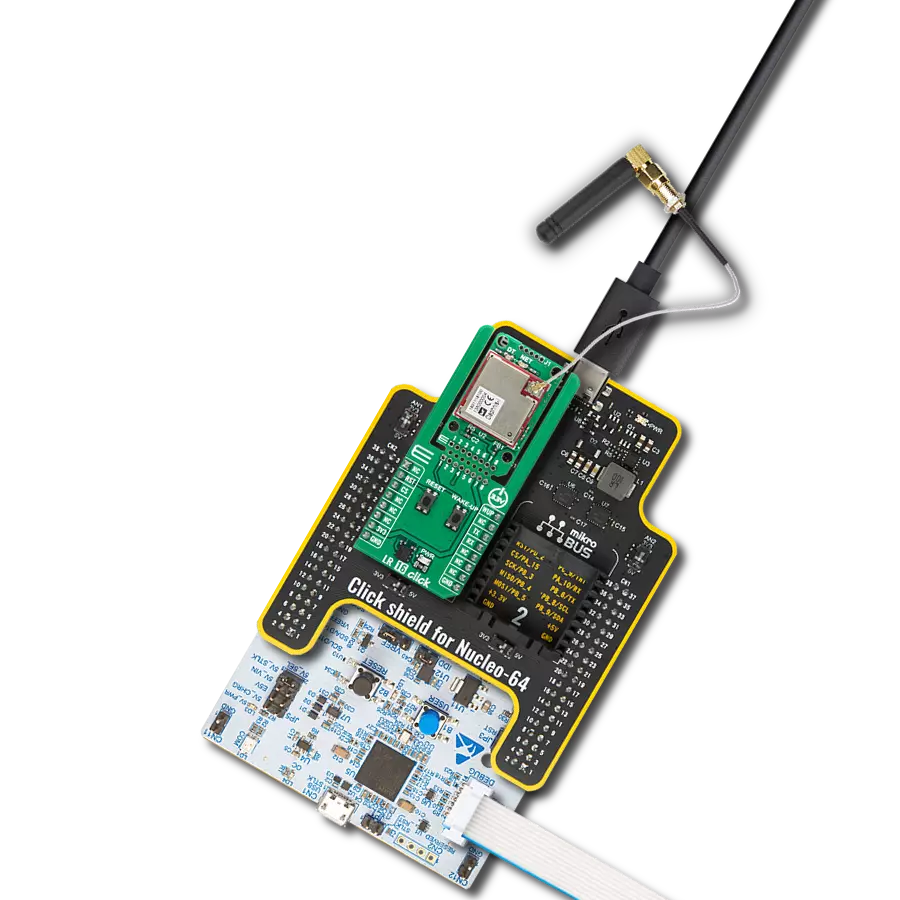
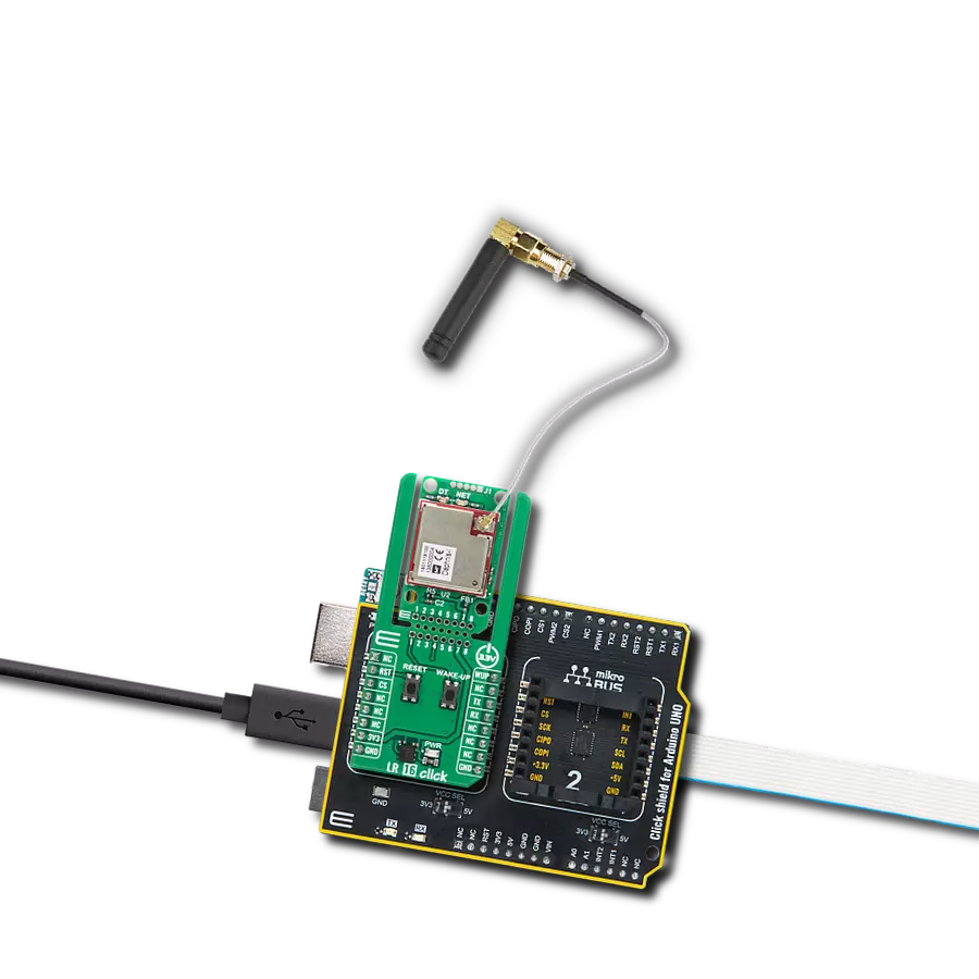
Nano LR Click
Dev. board
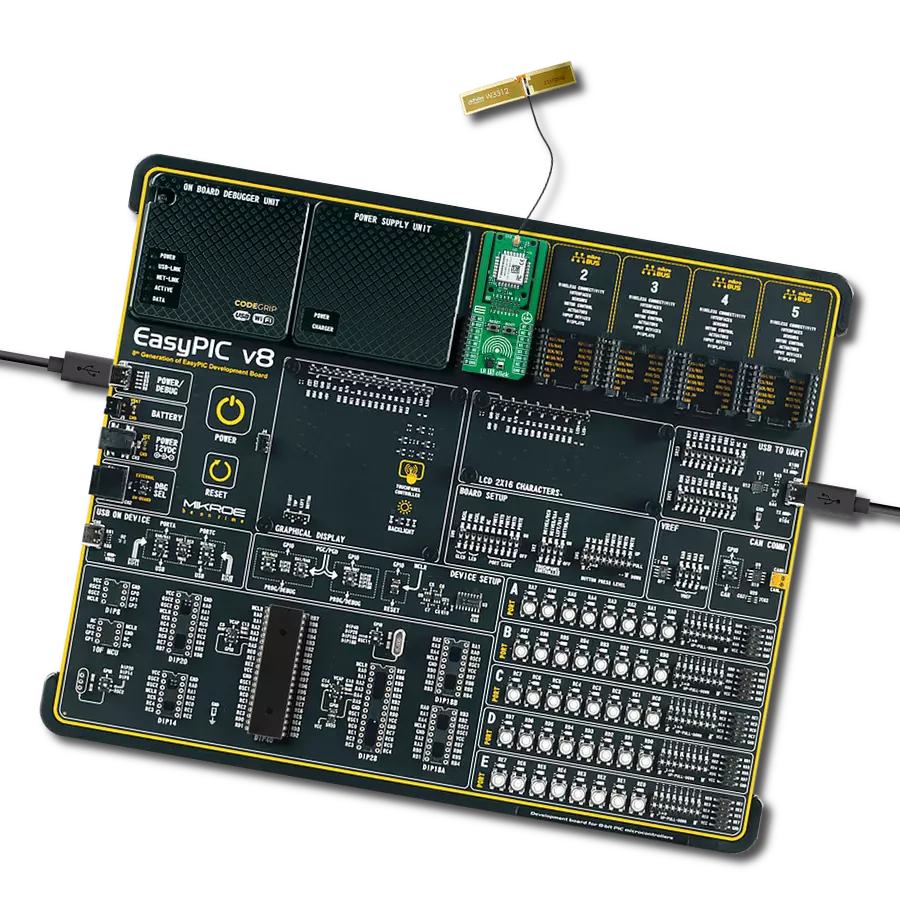
EasyAVR v7
Compiler
NECTO Studio
MCU
ATmega644P
Our 868MHz long-range transceiver is meticulously engineered to extend the reach of your wireless communication, allowing you to collect and transmit critical data from remote and challenging locations with unmatched reliability.
A
A
Hardware Overview
How does it work?
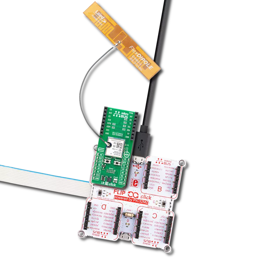
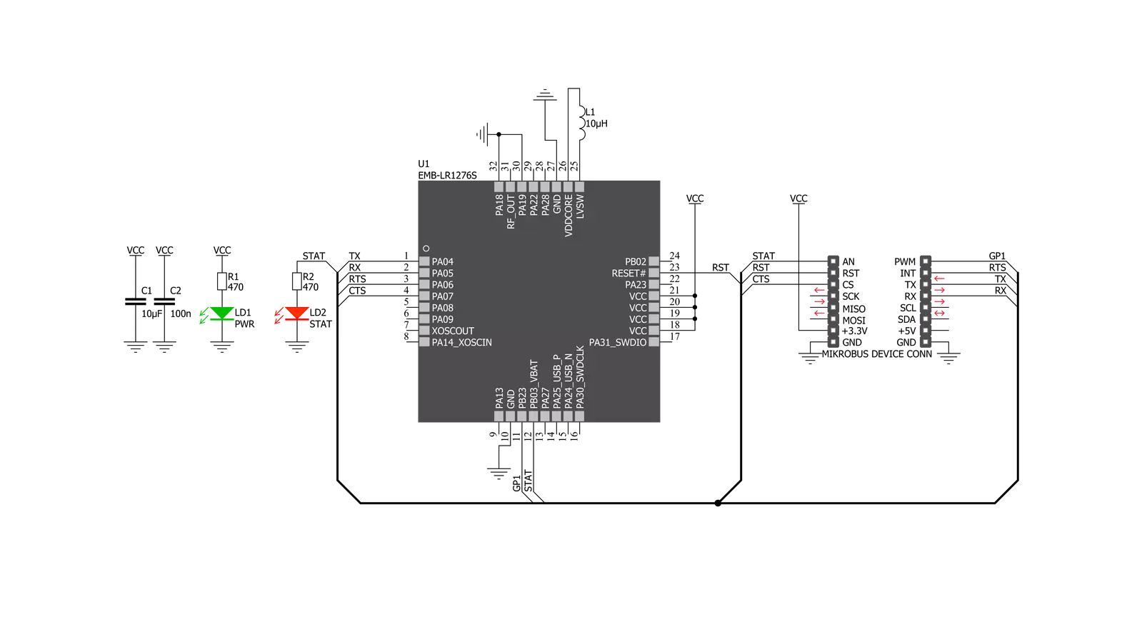
Nano LR Click is based on the EMB-LR1276S, a sub-1GHz wireless module that supports the LoRaWAN long-range wireless protocol based on the SAMR34 SiP from Embit. It offers a long-range spread spectrum communication with high interference immunity. Nano LR Click is ideal for various applications, such as IoT, home and building automation, wireless alarm and security systems, automated meter readings, industrial monitoring and control, and more. The EMB-LR1276S can be configured as an embedded microsystem or a simple data modem for
low-power applications in the 868MHz and 915MHz radio bands. It is equipped with up to 256 KB of Flash and up to 40 KB of SRAM, and it supports long-range and FSK modulation. Nano LR Click communicates with MCU using the UART interface with commonly used UART RX and TX pins with the hardware flow control pins UART CTS, RTS, RI (Clear to Send, Ready to Send, and Ring Indicator). Besides these pins, Nano LR Click also has GP1 and STAT pins, which are routed to the PWM and AN pins of the mikroBUS™ socket, respectively. STAT pin is also wired to a separate
LED indicator labeled STAT to enable quick and easy module status indication. Nano LR Click features the U.FL antenna connector with an impedance of 50Ω, so it can be equipped with the appropriate antenna that MIKROE offers. This Click board™ can be operated only with a 3.3V logic voltage level. The board must perform appropriate logic voltage level conversion before using MCUs with different logic levels. Also, it comes equipped with a library containing functions and an example code that can be used as a reference for further development.

Features overview
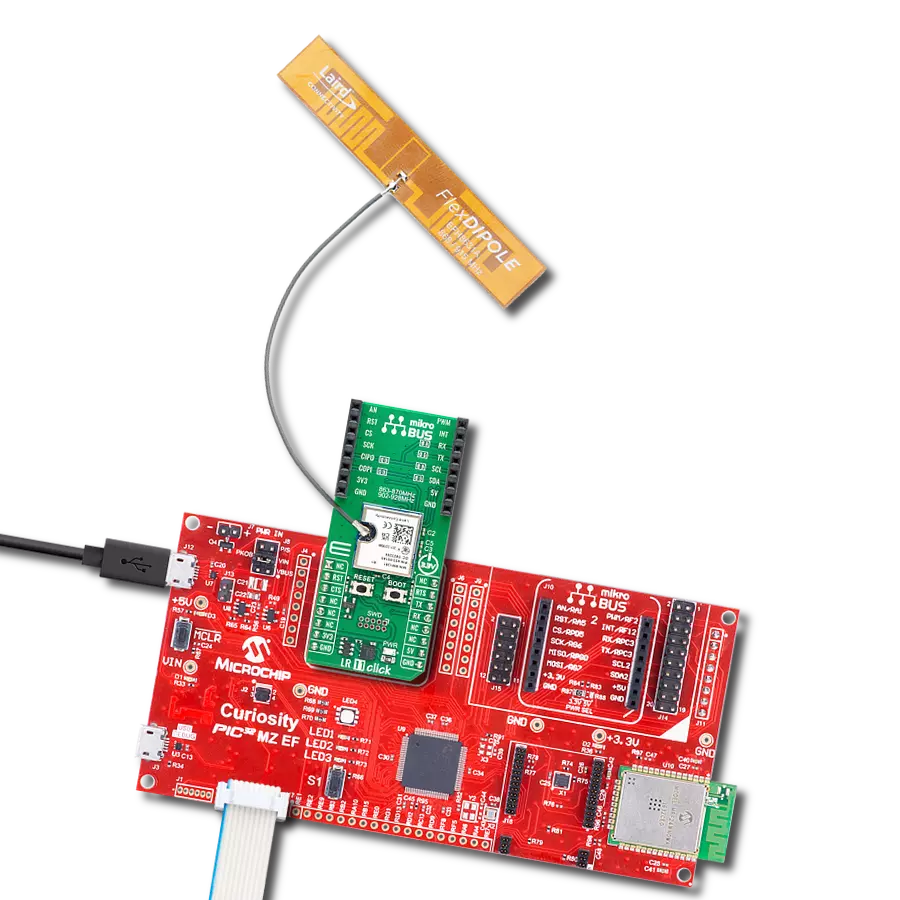
Development board
EasyAVR v7 is the seventh generation of AVR development boards specially designed for the needs of rapid development of embedded applications. It supports a wide range of 16-bit AVR microcontrollers from Microchip and has a broad set of unique functions, such as a powerful onboard mikroProg programmer and In-Circuit debugger over USB. The development board is well organized and designed so that the end-user has all the necessary elements in one place, such as switches, buttons, indicators, connectors, and others. With four different connectors for each port, EasyAVR v7 allows you to connect accessory boards, sensors, and custom electronics more
efficiently than ever. Each part of the EasyAVR v7 development board contains the components necessary for the most efficient operation of the same board. An integrated mikroProg, a fast USB 2.0 programmer with mikroICD hardware In-Circuit Debugger, offers many valuable programming/debugging options and seamless integration with the Mikroe software environment. Besides it also includes a clean and regulated power supply block for the development board. It can use a wide range of external power sources, including an external 12V power supply, 7-12V AC or 9-15V DC via DC connector/screw terminals, and a power source via the USB Type-B (USB-B)
connector. Communication options such as USB-UART and RS-232 are also included, alongside the well-established mikroBUS™ standard, three display options (7-segment, graphical, and character-based LCD), and several different DIP sockets which cover a wide range of 16-bit AVR MCUs. EasyAVR v7 is an integral part of the Mikroe ecosystem for rapid development. Natively supported by Mikroe software tools, it covers many aspects of prototyping and development thanks to a considerable number of different Click boards™ (over a thousand boards), the number of which is growing every day.

Microcontroller Overview
MCU Card / MCU

Architecture
AVR
MCU Memory (KB)
64
Silicon Vendor
Microchip
Pin count
40
RAM (Bytes)
4096
You complete me!
Accessories
Rubber Antenna GSM/GPRS Right Angle is the perfect companion for all GSM Click boards™ in our extensive lineup. This specialized antenna is designed to optimize your wireless connectivity with impressive features. With a wide frequency range spanning 824-894/1710-1990MHz or 890-960/1710-1890MHz, it can handle various frequency bands, ensuring a seamless and reliable connection. The antenna boasts an impedance of 50 Ohms and a gain of 2dB, enhancing signal reception and transmission. Its 70/180MHz bandwidth provides flexibility for diverse applications. The vertical polarization further enhances its performance. With a maximum input power capacity of 50W, this antenna ensures robust communication even under demanding conditions. Measuring a compact 50mm in length and featuring an SMA male connector, the Rubber Antenna GSM/GPRS Right Angle is a versatile and compact solution for your wireless communication needs.

IPEX-SMA cable is a type of RF (radio frequency) cable assembly. "IPEX" refers to the IPEX connector, a miniature coaxial connector commonly used in small electronic devices. "SMA" stands for SubMiniature Version A and is another coaxial connector commonly used in RF applications. An IPEX-SMA cable assembly has an IPEX connector on one end and an SMA connector on the other, allowing it to connect devices or components that use these specific connectors. These cables are often used in applications like WiFi or cellular antennas, GPS modules, and other RF communication systems where a reliable and low-loss connection is required.

Used MCU Pins
mikroBUS™ mapper
Take a closer look
Click board™ Schematic
Step by step
Project assembly

Start by selecting your development board and Click board™. Begin with the EasyAVR v7 as your development board.


Track your results in real time
Application Output
1. Application Output - In Debug mode, the 'Application Output' window enables real-time data monitoring, offering direct insight into execution results. Ensure proper data display by configuring the environment correctly using the provided tutorial.

2. UART Terminal - Use the UART Terminal to monitor data transmission via a USB to UART converter, allowing direct communication between the Click board™ and your development system. Configure the baud rate and other serial settings according to your project's requirements to ensure proper functionality. For step-by-step setup instructions, refer to the provided tutorial.

3. Plot Output - The Plot feature offers a powerful way to visualize real-time sensor data, enabling trend analysis, debugging, and comparison of multiple data points. To set it up correctly, follow the provided tutorial, which includes a step-by-step example of using the Plot feature to display Click board™ readings. To use the Plot feature in your code, use the function: plot(*insert_graph_name*, variable_name);. This is a general format, and it is up to the user to replace 'insert_graph_name' with the actual graph name and 'variable_name' with the parameter to be displayed.

Software Support
Library Description
This library contains API for Nano LR Click driver.
Key functions:
nanolr_send_data- This function sends data command depends on the chosen network protocol.nanolr_uart_isr- This function reads response bytes from the device and sets flag after each received byte.nanolr_rsp_rdy- This function checks if the response is ready.
Open Source
Code example
The complete application code and a ready-to-use project are available through the NECTO Studio Package Manager for direct installation in the NECTO Studio. The application code can also be found on the MIKROE GitHub account.
/*!
 * \file
 * \brief NanoLR Click example
 *
 * # Description
 * This example reads and processes data from Nano LR Clicks.
 *
 * The demo application is composed of two sections :
 *
 * ## Application Init
 * Initializes the driver, and performs the Click default configuration.
 *
 * ## Application Task
 * Depending on the selected mode, it reads all the received data or sends a desired message
 * every 2 seconds. All data is being displayed on the USB UART.
 *
 * ## Additional Function
 * - nanolr_process ( ) - Waits until a new message is ready, then parses it and displays the message
 *                        info on the USB UART.
 *
 *
 * \author MikroE Team
 *
 */
// ------------------------------------------------------------------- INCLUDES

#include "board.h"
#include "log.h"
#include "nanolr.h"
#include "string.h"

// ------------------------------------------------------------------ VARIABLES

// #define DEMO_APP_RECEIVER
#define DEMO_APP_TRANSMITTER

#define TEXT_TO_SEND "MikroE - Nano LR Click"

static nanolr_t nanolr;
static log_t logger;

// ------------------------------------------------------- ADDITIONAL FUNCTIONS

void nanolr_process( )
{
    uint8_t tmp_buf[ 200 ];

    // Clear RX buffer
    nanolr_generic_read( &nanolr, tmp_buf, 200 );

    while ( nanolr_rsp_rdy( &nanolr ) == 0 )
    {
        nanolr_uart_isr ( &nanolr );
        Delay_ms ( 1 );
    }

    nanolr_err_t error;
    nanolr_rsp_t response;

    error = nanolr_parser_rsp( &nanolr, &response );

    if ( error == 0 )
    {
        log_printf( &logger, "** Message received!\r\n" );
        log_printf( &logger, "** Message Length: %u\r\n", response.length );
        log_printf( &logger, "** Notification ID: 0x%.2X\r\n", ( uint16_t ) response.message_id );
        log_printf( &logger, "** Options: 0x%.4X\r\n", ( response.payload[ 0 ] << 8 ) | response.payload[ 1 ] );
        log_printf( &logger, "** RSSI in dBm: %d\r\n", ( response.payload[ 2 ] << 8 ) | ~response.payload[ 3 ] );
        log_printf( &logger, "** Source Address: 0x%.4X\r\n", ( response.payload[ 4 ] << 8 ) | response.payload[ 5 ] );
        log_printf( &logger, "** Destination Address: 0x%.4X\r\n", ( response.payload[ 6 ] << 8 ) | response.payload[ 7 ] );
        log_printf( &logger, "** Message Content: " );
        for ( uint16_t cnt = 8; cnt < response.length - 4; cnt++ )
        {
            log_printf( &logger, "%c", ( uint16_t ) response.payload[ cnt ] );
        }

        log_printf( &logger, "\r\n** Checksum: 0x%.2X\r\n", ( uint16_t ) response.crc );
    }
    else
    {
        log_printf( &logger, "** Message Error!\r\n" );
    }
    log_printf( &logger, "------------------------------------\r\n" );

    log_printf( &logger, "\r\n" );
}

// ------------------------------------------------------ APPLICATION FUNCTIONS

void application_init ( void )
{
    log_cfg_t log_cfg;
    nanolr_cfg_t cfg;

    /**
     * Logger initialization.
     * Default baud rate: 115200
     * Default log level: LOG_LEVEL_DEBUG
     * @note If USB_UART_RX and USB_UART_TX
     * are defined as HAL_PIN_NC, you will
     * need to define them manually for log to work.
     * See @b LOG_MAP_USB_UART macro definition for detailed explanation.
     */
    LOG_MAP_USB_UART( log_cfg );
    log_init( &logger, &log_cfg );
    log_info( &logger, "---- Application Init ----" );

    //  Click initialization.

    nanolr_cfg_setup( &cfg );
    NANOLR_MAP_MIKROBUS( cfg, MIKROBUS_1 );
    nanolr_init( &nanolr, &cfg );

    nanolr_default_cfg( &nanolr );

    log_printf( &logger,  "----  Nano LR Click ----\r\n" );

#ifdef DEMO_APP_RECEIVER
    log_printf( &logger,  "---- RECEIVER MODE ----\r\n" );
#endif

#ifdef DEMO_APP_TRANSMITTER
    log_printf( &logger,  "---- TRANSMITER MODE ----\r\n" );
#endif
    Delay_ms ( 1000 );
    Delay_ms ( 1000 );
}

void application_task ( void )
{
#ifdef DEMO_APP_RECEIVER
    nanolr_process( );
#endif

#ifdef DEMO_APP_TRANSMITTER
    nanolr_send_data( &nanolr, TEXT_TO_SEND, strlen( TEXT_TO_SEND ) );
    log_printf( &logger, "The message \"%s\" has been sent!\r\n", ( uint8_t * ) TEXT_TO_SEND );
    log_printf( &logger, "------------------------------------------------------------\r\n" );
    Delay_ms ( 1000 );
    Delay_ms ( 1000 );
#endif
}

int main ( void )
{
    /* Do not remove this line or clock might not be set correctly. */
    #ifdef PREINIT_SUPPORTED
    preinit();
    #endif

    application_init( );

    for ( ; ; )
    {
        application_task( );
    }

    return 0;
}

// ------------------------------------------------------------------------ END