Achieve accurate and consistent altitude data in diverse settings with KP236 and ATmega1284
Scaling new heights? Trust your altitude altimeter

Published Oct 14, 2023
Click board™
Altitude 5 Click
Dev. board
EasyAVR v7
Compiler
NECTO Studio
MCU
ATmega1284
A key instrument for measuring vertical distance, our altimeters are designed for accurate altitude tracking in various fields
A
A
Hardware Overview
How does it work?
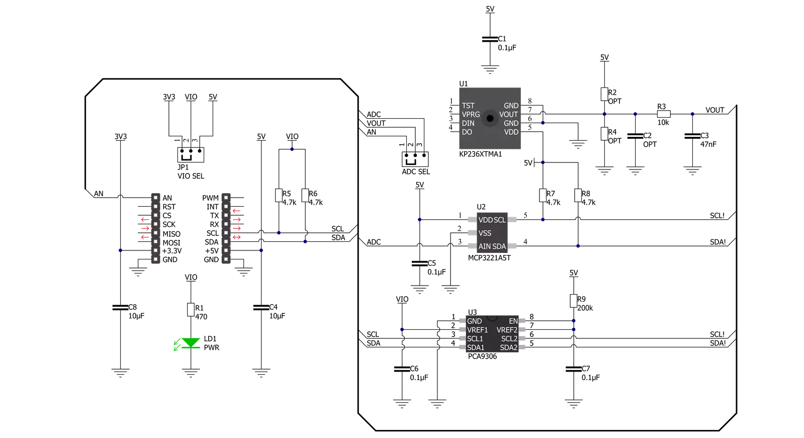
Altitude 5 Click is based on the KP236, a high-resolution analog barometric air pressure sensor based on a capacitive principle from Infineon. The KP236 surface is micro-machined with a monolithic integrated signal conditioning circuit implemented in BiCMOS technology that can measure pressure in a range from 40kPa up to 115kPa with an accuracy of ±1Pa over a wide operating temperature range at the industry’s lowest power. The KP236 is primarily developed for measuring barometric air pressure but can also be used in other application fields. The pressure is detected by an array of capacitive surface micro-machined sensor cells. The sensor cell output is amplified, temperature-compensated, and linearized to obtain an output voltage proportional
to the applied pressure. The transfer function for linearization is computed in the digital part of the sensor using a third-order polynomial calculation. The sensor converts pressure into an analog output signal; more precisely, the user can process the output signal in analog or digital form. The analog output voltage of the KP236 can be converted to a digital value using MCP3221, a successive approximation A/D converter with a 12-bit resolution from Microchip, using a 2-wire I2C compatible interface, or can be sent directly to an analog pin of the mikroBUS™ socket labeled as AN. Selection can be performed by onboard SMD jumper labeled ADC SEL to an appropriate position marked as AN and I2C. Using MCP3221 and I2C interface, data transfers at 100kbit/s
in the Standard and 400kbit/s in the Fast Mode Since the sensor for operation requires a 5V logic voltage level only, this Click board™ also features the PCA9306 voltage-level translator from Texas Instruments. The I2C interface bus lines are routed to the dual bidirectional voltage-level translator, allowing this Click board™ to work properly with both 3.3V and 5V MCUs. This Click board™ can operate with either 3.3V or 5V logic voltage levels selected via the VIO SEL jumper. This way, both 3.3V and 5V capable MCUs can use the communication lines properly. Also, this Click board™ comes equipped with a library containing easy-to-use functions and an example code that can be used as a reference for further development.


Features overview
Development board
EasyAVR v7 is the seventh generation of AVR development boards specially designed for the needs of rapid development of embedded applications. It supports a wide range of 16-bit AVR microcontrollers from Microchip and has a broad set of unique functions, such as a powerful onboard mikroProg programmer and In-Circuit debugger over USB. The development board is well organized and designed so that the end-user has all the necessary elements in one place, such as switches, buttons, indicators, connectors, and others. With four different connectors for each port, EasyAVR v7 allows you to connect accessory boards, sensors, and custom electronics more
efficiently than ever. Each part of the EasyAVR v7 development board contains the components necessary for the most efficient operation of the same board. An integrated mikroProg, a fast USB 2.0 programmer with mikroICD hardware In-Circuit Debugger, offers many valuable programming/debugging options and seamless integration with the Mikroe software environment. Besides it also includes a clean and regulated power supply block for the development board. It can use a wide range of external power sources, including an external 12V power supply, 7-12V AC or 9-15V DC via DC connector/screw terminals, and a power source via the USB Type-B (USB-B)
connector. Communication options such as USB-UART and RS-232 are also included, alongside the well-established mikroBUS™ standard, three display options (7-segment, graphical, and character-based LCD), and several different DIP sockets which cover a wide range of 16-bit AVR MCUs. EasyAVR v7 is an integral part of the Mikroe ecosystem for rapid development. Natively supported by Mikroe software tools, it covers many aspects of prototyping and development thanks to a considerable number of different Click boards™ (over a thousand boards), the number of which is growing every day.

Microcontroller Overview
MCU Card / MCU

Architecture
AVR
MCU Memory (KB)
128
Silicon Vendor
Microchip
Pin count
40
RAM (Bytes)
16384
Used MCU Pins
mikroBUS™ mapper
Take a closer look
Click board™ Schematic
Step by step
Project assembly

Start by selecting your development board and Click board™. Begin with the EasyAVR v7 as your development board.


Track your results in real time
Application Output
1. Application Output - In Debug mode, the 'Application Output' window enables real-time data monitoring, offering direct insight into execution results. Ensure proper data display by configuring the environment correctly using the provided tutorial.

2. UART Terminal - Use the UART Terminal to monitor data transmission via a USB to UART converter, allowing direct communication between the Click board™ and your development system. Configure the baud rate and other serial settings according to your project's requirements to ensure proper functionality. For step-by-step setup instructions, refer to the provided tutorial.

3. Plot Output - The Plot feature offers a powerful way to visualize real-time sensor data, enabling trend analysis, debugging, and comparison of multiple data points. To set it up correctly, follow the provided tutorial, which includes a step-by-step example of using the Plot feature to display Click board™ readings. To use the Plot feature in your code, use the function: plot(*insert_graph_name*, variable_name);. This is a general format, and it is up to the user to replace 'insert_graph_name' with the actual graph name and 'variable_name' with the parameter to be displayed.

Software Support
Library Description
This library contains API for Altitude 5 Click driver.
Key functions:
altitude5_get_altitude- Altitude 5 get altitude functionaltitude5_get_pressure- Altitude 5 get pressure functionaltitude5_get_adc_voltage- Altitude 5 get ADC voltage function
Open Source
Code example
The complete application code and a ready-to-use project are available through the NECTO Studio Package Manager for direct installation in the NECTO Studio. The application code can also be found on the MIKROE GitHub account.
/*!
 * @file main.c
 * @brief Altitude5 Click example
 *
 * # Description
 * This library contains API for Altitude 5 Click driver.
 * The demo application reads ADC value, calculate pressure and altitude.
 *
 * The demo application is composed of two sections :
 *
 * ## Application Init
 * Initializes I2C or analog driver and log UART.
 * After driver initialization the app set default settings.
 *
 * ## Application Task
 * This is an example that demonstrates the use of the Altitude 5 Click board™.
 * In this example, we read ADC values and
 * display the Pressure ( mBar ) and Altitude ( m ) data.
 * Results are being sent to the Usart Terminal where you can track their changes.
 *
 * @author Nenad Filipovic
 *
 */

#include "board.h"
#include "log.h"
#include "altitude5.h"

static altitude5_t altitude5;
static log_t logger;

void application_init ( void )
{
    log_cfg_t log_cfg;              /**< Logger config object. */
    altitude5_cfg_t altitude5_cfg;  /**< Click config object. */

    /**
     * Logger initialization.
     * Default baud rate: 115200
     * Default log level: LOG_LEVEL_DEBUG
     * @note If USB_UART_RX and USB_UART_TX
     * are defined as HAL_PIN_NC, you will
     * need to define them manually for log to work.
     * See @b LOG_MAP_USB_UART macro definition for detailed explanation.
     */
    LOG_MAP_USB_UART( log_cfg );
    log_init( &logger, &log_cfg );
    log_info( &logger, " Application Init " );

    // Click initialization.
    altitude5_cfg_setup( &altitude5_cfg );
    ALTITUDE5_MAP_MIKROBUS( altitude5_cfg, MIKROBUS_1 );
    err_t init_flag = altitude5_init( &altitude5, &altitude5_cfg );
    if ( I2C_MASTER_ERROR == init_flag )
    {
        log_error( &logger, " Application Init Error. " );
        log_info( &logger, " Please, run program again... " );

        for ( ; ; );
    }

    altitude5_default_cfg ( &altitude5 );
    log_info( &logger, " Application Task " );
    log_printf( &logger, "----------------------------\r\n" );
    Delay_ms ( 100 );
}

void application_task ( void )
{
    static float pressure;
    static float altitude;

    altitude5_get_pressure( &altitude5, &pressure );
    log_printf( &logger, " Pressure    : %.2f mBar \r\n", pressure );
    Delay_ms ( 100 );

    altitude5_get_altitude( &altitude5, &altitude );
    log_printf( &logger, " Altitude    : %.2f m \r\n", altitude );
    log_printf( &logger, "----------------------------\r\n" );
    Delay_ms ( 1000 );
}

int main ( void )
{
    /* Do not remove this line or clock might not be set correctly. */
    #ifdef PREINIT_SUPPORTED
    preinit();
    #endif

    application_init( );

    for ( ; ; )
    {
        application_task( );
    }

    return 0;
}

// ------------------------------------------------------------------------ END


