Achieve comprehensive and real-time data on air movement with LHDULTRAM012UB3 and ATmega324P
Venture into the future of air flow monitoring

Published Oct 14, 2023
Click board™
Air Flow Click
Dev. board
EasyAVR v7
Compiler
NECTO Studio
MCU
ATmega324P
Our air flow monitoring solution is designed to provide accurate and real-time insights into air circulation, catering to a wide spectrum of industries from HVAC to cleanrooms
A
A
Hardware Overview
How does it work?
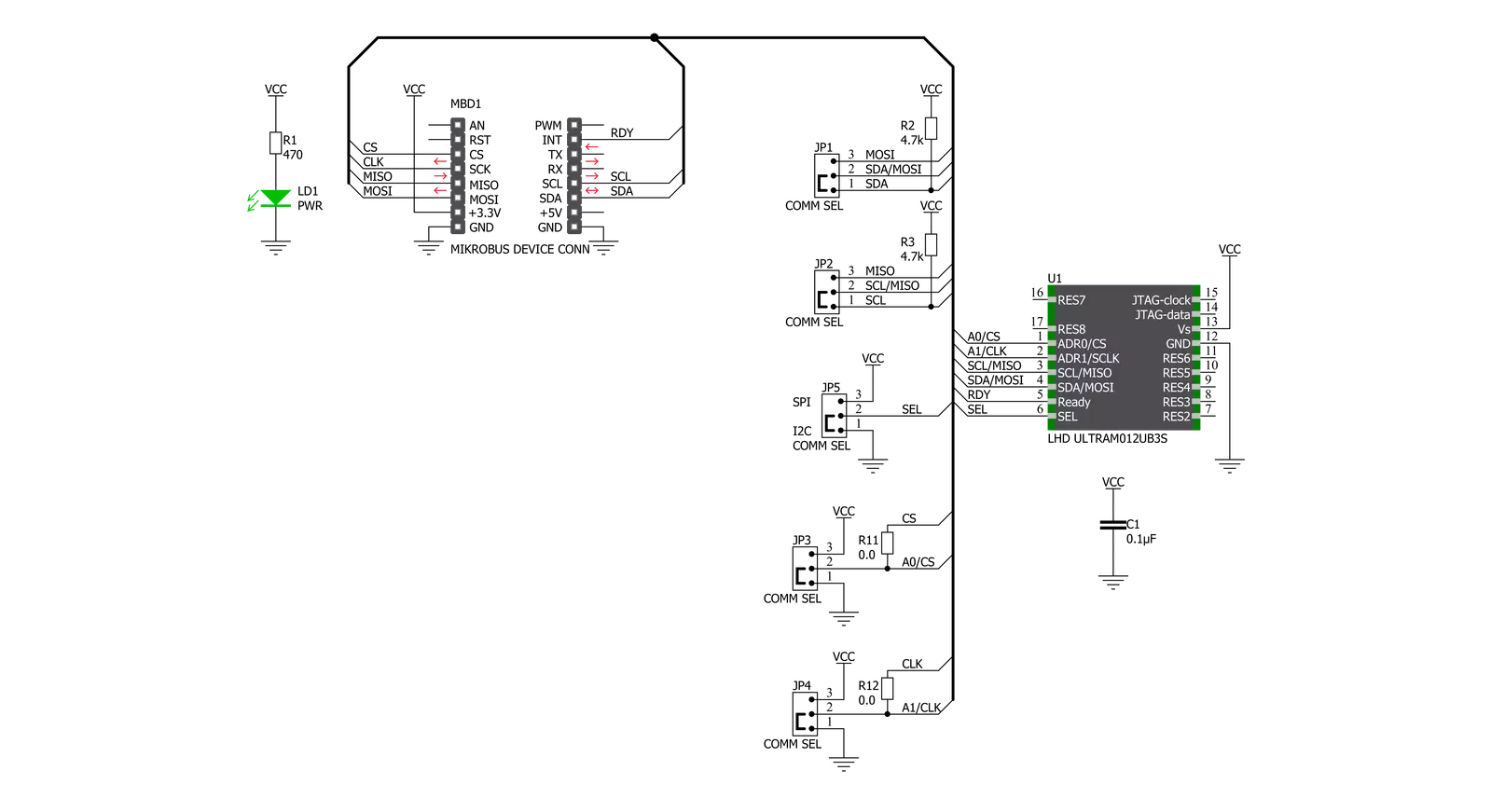
Air Flow Click is based on ses the LHDULTRAM012UB3, an LHD ULTRA series flow-based 2-in-1 differential pressure sensor from TE Connectivity Measurement Specialties. It comprises two combined calorimetric micro-flow channels and two sensor elements on a single chip. The first sensing element ensures precise measurement of low differential pressures with high resolution, and the second sensing element is optimized for pressures in the upper measuring range. A fast-response 24-bit onboard controller delivers precise measurements across the dynamic range from 0 to 1250Pa. The specific concept of the LHDULTRAM012UB3 ensures
continuous, highly reliable, economically efficient operation, outstanding long-term stability, and precision with patented real-time offset compensation and linearization techniques. The LHD ULTRA's high flow impedance ensures product-specific insensitivity to dust/moisture and minimal flow leakage. Air Flow Click allows for both I2C and SPI interfaces with a maximum frequency of 100kHz for I2C and 1MHz for SPI communication. The selection can be made by positioning SMD jumpers labeled COMM SEL to an appropriate position. Note that all the jumpers' positions must be on the same side, or the Click board™ may become unresponsive. While the I2C
interface is selected, the LHDULTRAM012UB3 allows the choice of the least significant bit (LSB) of its I2C slave address using the SMD jumpers labeled as A0 and A1 to an appropriate position marked as 0 and 1. Also, an additional ready signal, routed on the INT pin of the mikroBUS™ socket, is added, indicating that new data is ready for the host. This Click board™ can be operated only with a 3.3V logic voltage level. The board must perform appropriate logic voltage level conversion before using MCUs with different logic levels. Also, it comes equipped with a library containing functions and an example code that can be used as a reference for further development.


Features overview
Development board
EasyAVR v7 is the seventh generation of AVR development boards specially designed for the needs of rapid development of embedded applications. It supports a wide range of 16-bit AVR microcontrollers from Microchip and has a broad set of unique functions, such as a powerful onboard mikroProg programmer and In-Circuit debugger over USB. The development board is well organized and designed so that the end-user has all the necessary elements in one place, such as switches, buttons, indicators, connectors, and others. With four different connectors for each port, EasyAVR v7 allows you to connect accessory boards, sensors, and custom electronics more
efficiently than ever. Each part of the EasyAVR v7 development board contains the components necessary for the most efficient operation of the same board. An integrated mikroProg, a fast USB 2.0 programmer with mikroICD hardware In-Circuit Debugger, offers many valuable programming/debugging options and seamless integration with the Mikroe software environment. Besides it also includes a clean and regulated power supply block for the development board. It can use a wide range of external power sources, including an external 12V power supply, 7-12V AC or 9-15V DC via DC connector/screw terminals, and a power source via the USB Type-B (USB-B)
connector. Communication options such as USB-UART and RS-232 are also included, alongside the well-established mikroBUS™ standard, three display options (7-segment, graphical, and character-based LCD), and several different DIP sockets which cover a wide range of 16-bit AVR MCUs. EasyAVR v7 is an integral part of the Mikroe ecosystem for rapid development. Natively supported by Mikroe software tools, it covers many aspects of prototyping and development thanks to a considerable number of different Click boards™ (over a thousand boards), the number of which is growing every day.

Microcontroller Overview
MCU Card / MCU

Architecture
AVR
MCU Memory (KB)
32
Silicon Vendor
Microchip
Pin count
40
RAM (Bytes)
2048
Used MCU Pins
mikroBUS™ mapper
Take a closer look
Click board™ Schematic
Step by step
Project assembly

Start by selecting your development board and Click board™. Begin with the EasyAVR v7 as your development board.


Track your results in real time
Application Output
1. Application Output - In Debug mode, the 'Application Output' window enables real-time data monitoring, offering direct insight into execution results. Ensure proper data display by configuring the environment correctly using the provided tutorial.

2. UART Terminal - Use the UART Terminal to monitor data transmission via a USB to UART converter, allowing direct communication between the Click board™ and your development system. Configure the baud rate and other serial settings according to your project's requirements to ensure proper functionality. For step-by-step setup instructions, refer to the provided tutorial.

3. Plot Output - The Plot feature offers a powerful way to visualize real-time sensor data, enabling trend analysis, debugging, and comparison of multiple data points. To set it up correctly, follow the provided tutorial, which includes a step-by-step example of using the Plot feature to display Click board™ readings. To use the Plot feature in your code, use the function: plot(*insert_graph_name*, variable_name);. This is a general format, and it is up to the user to replace 'insert_graph_name' with the actual graph name and 'variable_name' with the parameter to be displayed.

Software Support
Library Description
This library contains API for Air Flow Click driver.
Key functions:
airflow_reset_device- Reset deviceairflow_get_differential_pressure- Reads differential pressureairflow_get_atmospheric_pressure- Reads atmospheric pressure and temperature
Open Source
Code example
The complete application code and a ready-to-use project are available through the NECTO Studio Package Manager for direct installation in the NECTO Studio. The application code can also be found on the MIKROE GitHub account.
/*!
 * @file main.c
 * @brief AirFlow Click example
 *
 * # Description
 * This example showcases ability for device to read differential
 * pressure, atmospheric pressure and ambient temperature.
 *
 * The demo application is composed of two sections :
 *
 * ## Application Init
 * Initialize host communication modules (UART, I2C/SPI). Read
 * electric signature data from device and logs it to terminal.
 *
 * ## Application Task
 * Reads differential pressure in Pa, atmospheric pressure in mBar
 * and ambient temperature in C every 500ms and logs read data.
 *
 * @author Luka Filipovic
 *
 */

#include "board.h"
#include "log.h"
#include "airflow.h"

static airflow_t airflow;
static log_t logger;

void application_init ( void )
{
    log_cfg_t log_cfg;  /**< Logger config object. */
    airflow_cfg_t airflow_cfg;  /**< Click config object. */

    /**
     * Logger initialization.
     * Default baud rate: 115200
     * Default log level: LOG_LEVEL_DEBUG
     * @note If USB_UART_RX and USB_UART_TX
     * are defined as HAL_PIN_NC, you will
     * need to define them manually for log to work.
     * See @b LOG_MAP_USB_UART macro definition for detailed explanation.
     */
    LOG_MAP_USB_UART( log_cfg );
    log_init( &logger, &log_cfg );
    Delay_ms ( 100 );
    log_info( &logger, " Application Init " );

    // Click initialization.
    airflow_cfg_setup( &airflow_cfg );
    AIRFLOW_MAP_MIKROBUS( airflow_cfg, MIKROBUS_1 );
    err_t init_flag  = airflow_init( &airflow, &airflow_cfg );
    if ( ( init_flag == I2C_MASTER_ERROR ) || ( init_flag == SPI_MASTER_ERROR ) )
    {
        log_error( &logger, " Application Init Error. " );
        log_info( &logger, " Please, run program again... " );

        for ( ; ; );
    }

    airflow_reset_device( &airflow );

    if ( airflow_default_cfg ( &airflow ) < 0 )
    {
        log_error( &logger, " Read" );
        log_info( &logger, " Please, run program again... " );
        for ( ; ; );
    }
    else
    {
        log_printf( &logger, "Firmware version: %d.%d\r\n", ( int16_t )airflow.major_fw_ver, ( int16_t )airflow.minor_fw_ver );
        //part number
        log_printf( &logger, "Part number: " );
        for ( uint8_t pn = 0; pn < 11; pn++ )
            log_printf( &logger, "%c", airflow.part_number[ pn ] );
        log_printf( &logger, "\r\n" );
        //lot number
        log_printf( &logger, "Lot number: " );
        for ( uint8_t pn = 0; pn < 7; pn++ )
            log_printf( &logger, "%c", airflow.lot_number[ pn ] );
        log_printf( &logger, "\r\n" );
        //pressure range
        log_printf( &logger, "Pressure range: %d\r\n", airflow.pressure_range );
        //output type
        log_printf( &logger, "Output type: %c\r\n", airflow.output_type );
        //scale factor
        log_printf( &logger, "Scale factor: %d\r\n", airflow.scale_factor );
        //calibration id
        log_printf( &logger, "Calibration ID: %s\r\n", airflow.calibration_id );
        //week
        log_printf( &logger, "Week: %d\r\n", ( int16_t )airflow.week );
        //year
        log_printf( &logger, "Year: %d\r\n", ( int16_t )airflow.year );
        //sequence number
        log_printf( &logger, "Sequence number: %d\r\n", airflow.sequence_number );
    }
    Delay_ms ( 1000 );
    Delay_ms ( 1000 );
    log_info( &logger, " Application Task " );
}

void application_task ( void )
{
    float pressure_data, temperature_data;

    airflow_get_differential_pressure( &airflow, &pressure_data );
    log_printf( &logger, "Differential pressure[Pa]: %.2f\r\n", pressure_data );
    airflow_get_atmospheric_pressure( &airflow, &pressure_data, &temperature_data );
    log_printf( &logger, "Atmospheric pressure[mBar]: %.2f\r\nTemperature[degC]: %.2f\r\n", pressure_data, temperature_data );
    log_printf( &logger, "***********************************************************\r\n" );
    Delay_ms ( 500 );
}

int main ( void )
{
    /* Do not remove this line or clock might not be set correctly. */
    #ifdef PREINIT_SUPPORTED
    preinit();
    #endif

    application_init( );

    for ( ; ; )
    {
        application_task( );
    }

    return 0;
}

// ------------------------------------------------------------------------ END


