Experience the next level of charging efficiency with MCP73113 and ATmega324P
Your devices deserve the best charging experience

Published Jun 08, 2023
Click board™
Charger 5 click
Dev. board
EasyAVR v7
Compiler
NECTO Studio
MCU
ATmega324P
Say goodbye to low battery anxiety with our reliable charging solution
A
A
Hardware Overview
How does it work?
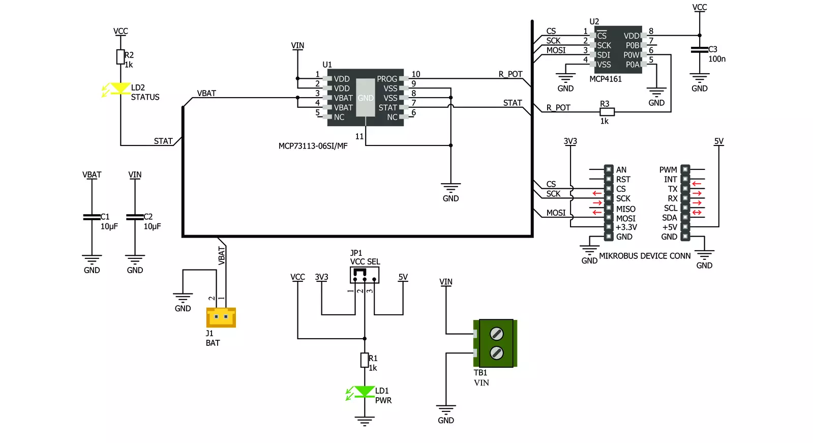
Charger 5 Click is based on the MCP73113, a single-cell Li-Po/Li-Ion battery charge from Microchip, along with the digital potentiometer chip labeled as MCP4161, from the same company. This click can easily and securely charge and fast-charge batteries on many devices that use 3.7V Li-Po/Li-Ion batteries. The constant charging current on the MCP73113 is set by a resistor connected between the PROG pin and the VCC; instead of using the conventional resistor, this board employs the MCP4161 digital potentiometer IC, which allows setting the constant charging current via the SPI interface. This way, the constant charging current can be set from 100mA to 950mA. The MCP73113 charger features several different battery charging protection and optimization schemes to keep the charging process safe and efficient. The undervoltage protection shuts the charger circuit down if the connected input voltage is below the threshold value.
The overvoltage protection will also put the device in shutdown mode if the input voltage exceeds the threshold value. Also, the connected input voltage should be 150mV greater than the battery voltage, or else it will remain in a power-down state. This prevents the battery from draining in case there's no input voltage. Therefore, the input voltage range should stay between 5V and 6.5V. The device is resistant to voltage spikes up to 18V on its input connector, but for proper operation, the input voltage should stay in the recommended voltage range. The connected battery voltage is constantly monitored. If it drops below the charging threshold and if all the other input voltage charging conditions are met, the charging process will start. When the battery is charged to the factory-set threshold, the charging will be stopped to prevent battery overcharging. The charging threshold for the MCP73113 charger IC used on this click is set to 4.2V.
If a Li-Ion battery is discharged below 3V, it must be pre-charged with around 10% of the full charge current. This means that the charging current, in this case, will be 10% of the fast charging current set by the MCP4161 digital potentiometer. Charger 5 click detects a short circuit on the battery connector. The short circuit is also reported in case of a faulty battery cell. If such an event occurs, the charger will enter the shutdown mode. The MCP73113 charger IC features thermal management too, which regulates the charging current, based on the die temperature. If the IC die is heated over 150°C, the device will be shut down. The onboard SMD jumper selector selects voltage for the digital potentiometer IC and SPI logic levels. There are also two onboard connectors. One connector is a screw terminal used to connect the external power supply (5V to 6.5V). The other connector is the Li-Po/Li-Ion battery 2.54mm header connector.

Features overview
Development board
EasyAVR v7 is the seventh generation of AVR development boards specially designed for the needs of rapid development of embedded applications. It supports a wide range of 16-bit AVR microcontrollers from Microchip and has a broad set of unique functions, such as a powerful onboard mikroProg programmer and In-Circuit debugger over USB. The development board is well organized and designed so that the end-user has all the necessary elements in one place, such as switches, buttons, indicators, connectors, and others. With four different connectors for each port, EasyAVR v7 allows you to connect accessory boards, sensors, and custom electronics more
efficiently than ever. Each part of the EasyAVR v7 development board contains the components necessary for the most efficient operation of the same board. An integrated mikroProg, a fast USB 2.0 programmer with mikroICD hardware In-Circuit Debugger, offers many valuable programming/debugging options and seamless integration with the Mikroe software environment. Besides it also includes a clean and regulated power supply block for the development board. It can use a wide range of external power sources, including an external 12V power supply, 7-12V AC or 9-15V DC via DC connector/screw terminals, and a power source via the USB Type-B (USB-B)
connector. Communication options such as USB-UART and RS-232 are also included, alongside the well-established mikroBUS™ standard, three display options (7-segment, graphical, and character-based LCD), and several different DIP sockets which cover a wide range of 16-bit AVR MCUs. EasyAVR v7 is an integral part of the Mikroe ecosystem for rapid development. Natively supported by Mikroe software tools, it covers many aspects of prototyping and development thanks to a considerable number of different Click boards™ (over a thousand boards), the number of which is growing every day.

Microcontroller Overview
MCU Card / MCU

Architecture
AVR
MCU Memory (KB)
32
Silicon Vendor
Microchip
Pin count
40
RAM (Bytes)
2048
You complete me!
Accessories
Li-Polymer Battery is the ideal solution for devices that demand a dependable and long-lasting power supply while emphasizing mobility. Its compatibility with mikromedia boards ensures easy integration without additional modifications. With a voltage output of 3.7V, the battery meets the standard requirements of many electronic devices. Additionally, boasting a capacity of 2000mAh, it can store a substantial amount of energy, providing sustained power for extended periods. This feature minimizes the need for frequent recharging or replacement. Overall, the Li-Polymer Battery is a reliable and autonomous power source, ideally suited for devices requiring a stable and enduring energy solution. You can find a more extensive choice of Li-Polymer batteries in our offer.

Used MCU Pins
mikroBUS™ mapper
Take a closer look
Click board™ Schematic
Step by step
Project assembly

Start by selecting your development board and Click board™. Begin with the EasyAVR v7 as your development board.


Software Support
Library Description
This library contains API for Charger 5 Click driver.
Key functions:
charger5_generic_write- Generic write functioncharger5_generic_read-Generic read functioncharger5_increment_wiper- Increment wiper function
Open Source
Code example
The complete application code and a ready-to-use project are available through the NECTO Studio Package Manager for direct installation in the NECTO Studio. The application code can also be found on the MIKROE GitHub account.
/*!
 * \file main.c
 * \brief Charger 5 Click example
 *
 * # Description
 * This example demonstrates the use of the Charger 5 Click board.
 *
 * The demo application is composed of two sections :
 *
 * ## Application Init
 * Initializes peripherals and pins used for the Charger 5 Click and prepares
 * the Charger 5 Click for properly working.
 *
 * ## Application Task
 * Demonstrates the use of driver functions. It will set charging current to
 * 500 mA, then will increment that value by 10 steps, and after that will
 * decrement it by 5 steps.
 *
 * ## Note
 * Increment/decrement command can only be issued to volatile memory locations.
 *
 * \author Nemanja Medakovic
 *
 */
// ------------------------------------------------------------------- INCLUDES

#include "board.h"
#include "log.h"
#include "charger5.h"

// ------------------------------------------------------------------ VARIABLES

static charger5_t charger5;
static log_t console;

// ------------------------------------------------------ APPLICATION FUNCTIONS

void application_init( void )
{
    charger5_cfg_t charger5_cfg;
    log_cfg_t console_cfg;

    //  Click initialization.
    charger5_cfg_setup( &charger5_cfg );
    CHARGER5_MAP_MIKROBUS( charger5_cfg, MIKROBUS_1 );
    charger5_init( &charger5, &charger5_cfg );
    charger5_default_cfg( &charger5 );

    /**
     * Logger initialization.
     * Default baud rate: 115200
     * Default log level: LOG_LEVEL_DEBUG
     * @note If USB_UART_RX and USB_UART_TX
     * are defined as HAL_PIN_NC, you will
     * need to define them manually for log to work.
     * See @b LOG_MAP_USB_UART macro definition for detailed explanation.
     */
    LOG_MAP_USB_UART( console_cfg );
    log_init( &console, &console_cfg );
    log_printf( &console, "***  Charger 5 initialization done  ***\r\n" );
    log_printf( &console, "***************************************\r\n" );
}

void application_task( void )
{
    charger5_generic_write( &charger5, CHARGER5_REG_WIPER0_VOL,
                            CHARGER5_CURRENT_500MA );
    log_printf( &console, "Output current is set to 500 mA.\r\n" );
    Delay_ms ( 1000 );
    Delay_ms ( 1000 );
    Delay_ms ( 1000 );

    charger5_increment_wiper( &charger5, CHARGER5_REG_WIPER0_VOL,
                              CHARGER5_STEPS_10 );
    log_printf( &console, "Output current value is incremented by 10 steps.\r\n" );
    Delay_ms ( 1000 );
    Delay_ms ( 1000 );
    Delay_ms ( 1000 );

    charger5_decrement_wiper( &charger5, CHARGER5_REG_WIPER0_VOL,
                              CHARGER5_STEPS_5 );
    log_printf( &console, "Output current value is decremented by 5 steps.\r\n" );
    Delay_ms ( 1000 );
    Delay_ms ( 1000 );
    Delay_ms ( 1000 );
}

int main ( void )
{
    /* Do not remove this line or clock might not be set correctly. */
    #ifdef PREINIT_SUPPORTED
    preinit();
    #endif

    application_init( );

    for ( ; ; )
    {
        application_task( );
    }

    return 0;
}


// ------------------------------------------------------------------------ END
Additional Support
Resources
Category:Battery charger


