Transmit your data reliably with MICRF114 and ATmega1284
Reliable transmitting, unlimited possibilities

Published Nov 07, 2023
Click board™
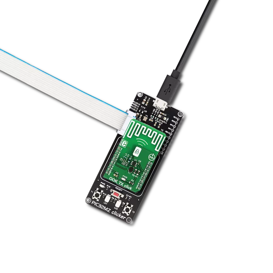
OOK TX Click
Dev. board
EasyAVR v7
Compiler
NECTO Studio
MCU
ATmega1284
With our 433MHz wireless transmitter, you're in control, enabling seamless communication and conquering the limitations of wired connections, making your life easier and more efficient
A
A
Hardware Overview
How does it work?
OOK TX Click is based on the MICRF114, a 285MHz to 445MHz low power integrated RF transmitter, from Microchip. The working principle of this device is based on the encoding of information and embedding it in a radio signal. The OOK modulation is a way to encode information and assemble it into radio signals which can be transmitted and received wirelessly. Generally, the OOK modulation is a subtype of the ASK modulation, but it is of a binary type. OOK is an abbreviate for the Off-On Keying, which perfectly describes this type of modulation. The presence of the carrier signal is recognized as the logical 1, while the absence of a carrier signal is recognized as the logical 0. This method is more immune to noise and interferences than the ASK modulation, and it allows for greater communication distance to be achieved. The transmission signal of OOK TX click is generated by the internal synthesizer section of the MICRF114 IC, which operates at a single frequency. The external oscillator with the base frequency of 13.56 MHz is used so that the RF signal frequency is 433.95MHz, a perfect match for the OOK RX click, which operates on the exact same frequency. The MICRF114 IC has a single RF output pin, which can be easily matched with the onboard single pole PCB trace antenna. The
communication with the MICRF114 IC is done through the 2-Wire (I2C) interface. The communication is unidirectional - from the MCU to the MICRF114. The transmission parameters are kept within one 16bit register, so the configuration is simple and easy. On a power-on reset event (POR), the device is loaded with the default values and it is necessary to initialize it, before starting the transmission. The device features auto calibration, which is engaged after each POR, although the MCU can request the recalibration. The recalibration is required if the operating frequency is changed, so it is usually not requested on the fly. There are two modes of operation: Sleep mode and Transmit mode. The MCU initializes the communication by sending the Start signal over the communication bus. The Start signal is followed by the mandatory Control bits and optional Configuration bits. After the rising edge of the last bus clock pulse on the SCK pin of the MICRF114 IC, the wake-up sequence will start and the device goes into Transmit mode. The MCU should keep the clock line at a LOW state and after waiting for the maximum wake-up time interval, the transmission can start. At this moment, the communication becomes asynchronous and the device directly modulates
the carrier signal with the data incoming on the SDI pin. After receiving the Stop signal on the bus, the transmission is ended and the device reverts to the Sleep mode. While in Sleep mode, most of the sections are powered down and the power consumption is minimal. The SCK pin of the MICRF114 IC is routed to the mikroBUS™ SCL pin, while the SDI pin of the MICRF114 IC is routed to the mikroBUS™ SDA pin. The included MikroElektronika libraries contain all the functions needed for an easy and proper configuration of the transmit parameters and communication itself. The included demo application can be used as a reference for a future design. Although OOK TX click features a programmable output power, the small PCB trace antenna limits the transmitted signal power, so it can stay within the European Telecommunications Standards Institute (ETSI) limitations. The device complies with the FCC and IC regulations. For this reason, an external SMA connector is not used. OOK TX click comes equipped with the pull-up resistors on its 2-Wire (I2C) communication lines. It is meant to be powered only from the 3.3V rail of the mikroBUS™.

Features overview
Development board
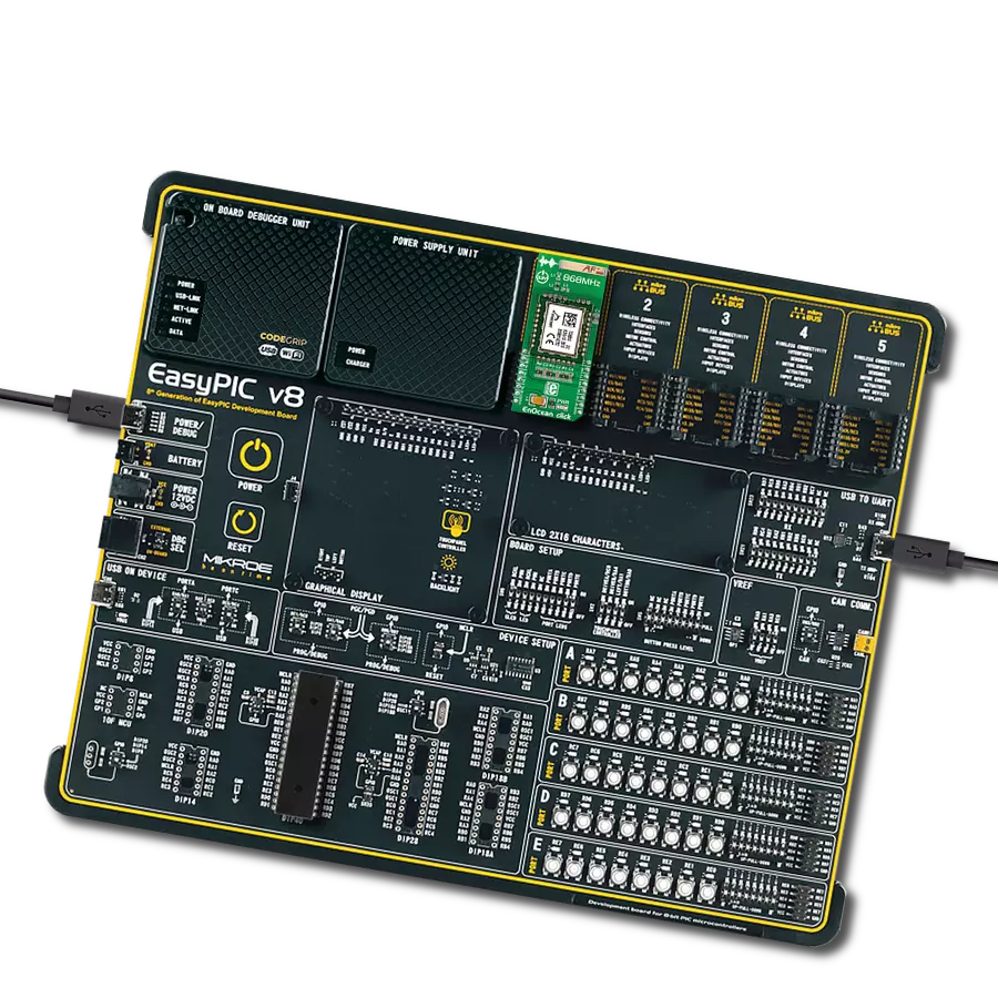
EasyAVR v7 is the seventh generation of AVR development boards specially designed for the needs of rapid development of embedded applications. It supports a wide range of 16-bit AVR microcontrollers from Microchip and has a broad set of unique functions, such as a powerful onboard mikroProg programmer and In-Circuit debugger over USB. The development board is well organized and designed so that the end-user has all the necessary elements in one place, such as switches, buttons, indicators, connectors, and others. With four different connectors for each port, EasyAVR v7 allows you to connect accessory boards, sensors, and custom electronics more
efficiently than ever. Each part of the EasyAVR v7 development board contains the components necessary for the most efficient operation of the same board. An integrated mikroProg, a fast USB 2.0 programmer with mikroICD hardware In-Circuit Debugger, offers many valuable programming/debugging options and seamless integration with the Mikroe software environment. Besides it also includes a clean and regulated power supply block for the development board. It can use a wide range of external power sources, including an external 12V power supply, 7-12V AC or 9-15V DC via DC connector/screw terminals, and a power source via the USB Type-B (USB-B)
connector. Communication options such as USB-UART and RS-232 are also included, alongside the well-established mikroBUS™ standard, three display options (7-segment, graphical, and character-based LCD), and several different DIP sockets which cover a wide range of 16-bit AVR MCUs. EasyAVR v7 is an integral part of the Mikroe ecosystem for rapid development. Natively supported by Mikroe software tools, it covers many aspects of prototyping and development thanks to a considerable number of different Click boards™ (over a thousand boards), the number of which is growing every day.

Microcontroller Overview
MCU Card / MCU

Architecture
AVR
MCU Memory (KB)
128
Silicon Vendor
Microchip
Pin count
40
RAM (Bytes)
16384
Used MCU Pins
mikroBUS™ mapper
Take a closer look
Click board™ Schematic

Step by step
Project assembly

Start by selecting your development board and Click board™. Begin with the EasyAVR v7 as your development board.


Software Support
Library Description
This library contains API for OOK TX Click driver.
Key functions:
ooktx_communication_init- This function initiates the OOK communication.ooktx_communication_stop- This function stops the OOK communication.ooktx_communication_transmit- This function transmits data in the OOK communication.
Open Source
Code example
The complete application code and a ready-to-use project are available through the NECTO Studio Package Manager for direct installation in the NECTO Studio. The application code can also be found on the MIKROE GitHub account.
/*!
 * @file main.c
 * @brief OOK TX Click Example.
 *
 * # Description
 * This example demonstrates the use of OOK TX Click board by sending
 * a predefined message to the receiver.
 *
 * The demo application is composed of two sections :
 *
 * ## Application Init
 * Initializes the driver and logger.
 *
 * ## Application Task
 * Sends a predefined message every 3 seconds and displays it on the USB UART.
 *
 * @note
 * The OOK RX Click board is a compatible receiver for the OOK TX Click.
 * Here are a few steps for troubleshooting if you are experiencing issues running
 * this example:
 *  - Check the MCU clock configuration, use an external oscillator instead of the MCU's
 * internal one for better accuracy on manchester data rate delay.
 *  - Measure the actual data rate on the data line and adjust the OOKTX_MAN_BIT_LEN_US
 * value accordingly.
 *
 * @author Stefan Filipovic
 *
 */

#include "board.h"
#include "log.h"
#include "ooktx.h"

#define OOKTX_PREAMBLE          0x5AA5      /**< Packet preamble word. */
#define OOKTX_MESSAGE           "MIKROE"    /**< Text message to send. */

static ooktx_t ooktx;           /**< OOK TX Click driver object. */
static log_t logger;            /**< Logger object. */

/**
 * @brief OOK TX send data function.
 * @details This function builds and sends a packet of data.
 * The packet format is as follows (MSB first, manchester IEEE 802.3):
 * OOKTX_TRAINING_BYTES, PREABMLE, LEN, DATA_IN, CRC16 (calculated from whole packet excluding training bytes).
 * @param[in] ctx : Click context object.
 * See #ooktx_t object definition for detailed explanation.
 * @param[in] preamble : Preamble word.
 * @param[in] data_in : Data buffer.
 * @param[in] len : Number of bytes in data buffer.
 * @return None.
 * @note Default manchester bit length is set to 2000us.
 */
static void ooktx_send_data ( ooktx_t *ctx, uint16_t preamble, uint8_t *data_in, uint8_t len );

/**
 * @brief Manchester encode bits.
 * @details This function encodes a data byte to manchester word (IEEE 802.3).
 * @return Manchester word.
 * @note None.
 */
static uint16_t ooktx_man_encode ( uint8_t data_in );

/**
 * @brief Reflect bits.
 * @details This function reflects a desired number of bits in data.
 * @return Reflected data.
 * @note None.
 */
static uint16_t ooktx_reflect_bits( uint16_t data_in, uint8_t len );

/**
 * @brief CRC-16/MAXIM calculation for CRC16 function.
 * @details This function calculates CRC16 with parameteres:
 * @li @c  Width 16 bit
 * @li @c  Polynomial 0x8005 ( x16 + x15 + x2 + x0 )
 * @li @c  Initialization 0x0000
 * @li @c  Reflect input True
 * @li @c  Reflect output True
 * @li @c  Final Xor 0xFFFF
 * @li @c  Example { 69, 00 } - 0xAFD1
 * @param[in] data_buf : Array of bytes to calculate crc from.
 * @param[in] len : Number of bytes to calculate crc from.
 * @return Calculated CRC.
 * @note None.
 */
static uint16_t ooktx_calculate_crc16 ( uint8_t *data_buf, uint16_t len );

void application_init ( void )
{
    log_cfg_t log_cfg;          /**< Logger config object. */
    ooktx_cfg_t ooktx_cfg;      /**< Click config object. */

    /**
     * Logger initialization.
     * Default baud rate: 115200
     * Default log level: LOG_LEVEL_DEBUG
     * @note If USB_UART_RX and USB_UART_TX
     * are defined as HAL_PIN_NC, you will
     * need to define them manually for log to work.
     * See @b LOG_MAP_USB_UART macro definition for detailed explanation.
     */
    LOG_MAP_USB_UART( log_cfg );
    log_init( &logger, &log_cfg );
    log_info( &logger, " Application Init " );

    // Click initialization.
    ooktx_cfg_setup( &ooktx_cfg );
    OOKTX_MAP_MIKROBUS( ooktx_cfg, MIKROBUS_1 );
    if ( DIGITAL_OUT_UNSUPPORTED_PIN == ooktx_init( &ooktx, &ooktx_cfg ) )
    {
        log_error( &logger, " Communication init." );
        for ( ; ; );
    }

    log_info( &logger, " Application Task " );
}

void application_task ( void )
{
    log_printf ( &logger, " Sending data: %s\r\n\n", ( char * ) OOKTX_MESSAGE );
    ooktx_send_data ( &ooktx, OOKTX_PREAMBLE, OOKTX_MESSAGE, strlen ( OOKTX_MESSAGE ) );
    Delay_ms ( 1000 );
    Delay_ms ( 1000 );
    Delay_ms ( 1000 );
}

int main ( void )
{
    /* Do not remove this line or clock might not be set correctly. */
    #ifdef PREINIT_SUPPORTED
    preinit();
    #endif

    application_init( );

    for ( ; ; )
    {
        application_task( );
    }

    return 0;
}

static void ooktx_send_data ( ooktx_t *ctx, uint16_t preamble, uint8_t *data_in, uint8_t len )
{
    uint8_t training[ ] = OOKTX_TRAINING_BYTES;
    uint8_t packet_buf[ OOKTX_MAX_DATA_LEN + 5 ] = { 0 };
    uint16_t crc = 0;
    uint16_t man_data = 0;
    uint8_t byte_cnt = 0;
    uint8_t bit_cnt = 0;

    packet_buf[ 0 ] = ( uint8_t ) ( ( preamble >> 8 ) & 0xFF );
    packet_buf[ 1 ] = ( uint8_t ) ( preamble & 0xFF );
    packet_buf[ 2 ] = len;
    memcpy ( &packet_buf[ 3 ], data_in, len );
    crc = ooktx_calculate_crc16 ( packet_buf, len + 3 );
    packet_buf[ len + 3 ] = ( uint8_t ) ( ( crc >> 8 ) & 0xFF );
    packet_buf[ len + 4 ] = ( uint8_t ) ( crc & 0xFF );

    ooktx_start ( ctx, OOKTX_CALIB_ENABLE, OOKTX_CFG_ENABLE, OOKTX_CFG_DEFAULT );
    Delay_10ms( );
    // Send training bytes first
    for ( byte_cnt = 0; byte_cnt < sizeof ( training ); byte_cnt++ )
    {
        man_data = ooktx_man_encode ( training[ byte_cnt ] );
        for ( bit_cnt = 0; bit_cnt < 16; bit_cnt++ )
        {
            if ( man_data & OOKTX_MAN_MSB )
            {
                ooktx_set_data_pin ( ctx );
            }
            else
            {
                ooktx_clear_data_pin ( ctx );
            }
            man_data <<= 1;
            Delay_us ( OOKTX_MAN_BIT_LEN_US / 2 );
        }
    }
    // Send the packet bytes
    for ( byte_cnt = 0; byte_cnt < ( len + 5 ); byte_cnt++ )
    {
        man_data = ooktx_man_encode ( packet_buf[ byte_cnt ] );
        for ( bit_cnt = 0; bit_cnt < 16; bit_cnt++ )
        {
            if ( man_data & OOKTX_MAN_MSB )
            {
                ooktx_set_data_pin ( ctx );
            }
            else
            {
                ooktx_clear_data_pin ( ctx );
            }
            man_data <<= 1;
            Delay_us ( OOKTX_MAN_BIT_LEN_US / 2 );
        }
    }
    Delay_10ms( );
    ooktx_stop ( ctx );
}

static uint16_t ooktx_man_encode ( uint8_t data_in )
{
    uint16_t man_data = 0;

    for ( uint8_t bit_cnt = 0; bit_cnt < 8; bit_cnt++ )
    {
        man_data <<= 2;
        if ( data_in & ( 0x80 >> bit_cnt ) )
        {
            man_data |= 1;  // 1: low going to a high
        }
        else
        {
            man_data |= 2;  // 0: high going to a low
        }
    }
    return man_data;
}

static uint16_t ooktx_reflect_bits( uint16_t data_in, uint8_t len )
{
    uint16_t data_out = 0;
    for ( uint16_t cnt = 0; cnt < len; cnt++ )
    {
        data_out |= ( ( data_in >> cnt ) & 1 ) << ( len - cnt - 1 );
    }
    return data_out;
}

static uint16_t ooktx_calculate_crc16( uint8_t *data_buf, uint16_t len )
{
    uint16_t crc16 = 0x0000;
    for ( uint16_t cnt = 0; cnt < len; cnt++ )
    {
        crc16 ^= ( ooktx_reflect_bits( data_buf[ cnt ], 8 ) << 8 );
        for ( uint8_t bit_cnt = 0; bit_cnt < 8; bit_cnt++ )
        {
            if ( crc16 & 0x8000 )
            {
                crc16 = ( crc16 << 1 ) ^ 0x8005;
            }
            else
            {
                crc16 <<= 1;
            }
        }
    }
    return ooktx_reflect_bits( crc16, 16 ) ^ 0xFFFF;
}

// ------------------------------------------------------------------------ END