Elevate your altitude measurements with confidence using MS5607-02BA03 and ATmega1284
Rise above, embrace the altitude

Published Oct 12, 2023
Click board™
Altitude 2 Click
Dev. board
EasyAVR v7
Compiler
NECTO Studio
MCU
ATmega1284
Our altitude measurement solution is your passport to exploring the world from a new perspective, offering impeccable accuracy and reliability for aviation, adventure sports, and beyond.
A
A
Hardware Overview
How does it work?
Altitude 2 Click is based on the MS5607, a barometric pressure sensor IC with the stainless steel cap from TE Connectivity. It provides very accurate measurements of temperature and atmospheric pressure, which can be used to calculate the altitude with a very high resolution of 20cm per step. Besides that, the device also includes features such as the ultra-low noise delta-sigma 24bit ADC, low power consumption, fast conversion times, pre-programmed unique compensation values, and more. Low count of external components requirement, along with the simple interface which requires no extensive configuration programming, makes this sensor very attractive for building altitude or air pressure measuring applications. To measure the air pressure with a reasonable accuracy, the ambient temperature should also be taken into the consideration. The sensor component of the Altitude 2 click provides an accurate ambient temperature measurement, which can be used
to extract the compensated air pressure value from the readings. It can be set to work with both SPI and I2C communication protocol, by switching a few onboard jumpers. With its low power consumption, it is a great solution for using it in various mobile altimeter applications, such as the bike computers, variometers, data loggers, mobile altimeter and barometer stations, weather stations, and similar. The Click board™ offers a choice between using the I2C and SPI communication protocol. When I2C communication protocol is selected, all jumpers labeled as the COMM SEL, should be set to the I2C position (left). When SPI is selected, all these jumpers should be moved to the SPI position (right). When I2C protocol is selected, another onboard SMD jumper is used to set the LSB bit of the slave I2C address. Please note that when selecting I2C or SPI protocol, all of the COMM SEL SMD jumpers should be set at the same position (all to SPI, or all to I2C). Mixed position settings
can result in the unresponsiveness of the Click board™. There are no additional pins routed from the sensor IC, other than the lines used for the communication: SPI lines, labeled as SDI, SDO, SCK, and CS, and I2C lines, labeled as SDA and SCL. These lines are routed to the appropriate mikroBUS™ pins, used for I2C and SPI communication. The I2C lines, along with the CS line are pulled to a HIGH logic level by the onboard resistors. Please note that the Click board™ supports only 3.3V MCUs and it is not intended to be connected or controlled via the 5V MCU without a proper level shifting circuitry. This Click board™ can be operated only with a 3.3V logic voltage level. The board must perform appropriate logic voltage level conversion before using MCUs with different logic levels. Also, it comes equipped with a library containing functions and an example code that can be used as a reference for further development.


Features overview
Development board
EasyAVR v7 is the seventh generation of AVR development boards specially designed for the needs of rapid development of embedded applications. It supports a wide range of 16-bit AVR microcontrollers from Microchip and has a broad set of unique functions, such as a powerful onboard mikroProg programmer and In-Circuit debugger over USB. The development board is well organized and designed so that the end-user has all the necessary elements in one place, such as switches, buttons, indicators, connectors, and others. With four different connectors for each port, EasyAVR v7 allows you to connect accessory boards, sensors, and custom electronics more
efficiently than ever. Each part of the EasyAVR v7 development board contains the components necessary for the most efficient operation of the same board. An integrated mikroProg, a fast USB 2.0 programmer with mikroICD hardware In-Circuit Debugger, offers many valuable programming/debugging options and seamless integration with the Mikroe software environment. Besides it also includes a clean and regulated power supply block for the development board. It can use a wide range of external power sources, including an external 12V power supply, 7-12V AC or 9-15V DC via DC connector/screw terminals, and a power source via the USB Type-B (USB-B)
connector. Communication options such as USB-UART and RS-232 are also included, alongside the well-established mikroBUS™ standard, three display options (7-segment, graphical, and character-based LCD), and several different DIP sockets which cover a wide range of 16-bit AVR MCUs. EasyAVR v7 is an integral part of the Mikroe ecosystem for rapid development. Natively supported by Mikroe software tools, it covers many aspects of prototyping and development thanks to a considerable number of different Click boards™ (over a thousand boards), the number of which is growing every day.

Microcontroller Overview
MCU Card / MCU

Architecture
AVR
MCU Memory (KB)
128
Silicon Vendor
Microchip
Pin count
40
RAM (Bytes)
16384
Used MCU Pins
mikroBUS™ mapper
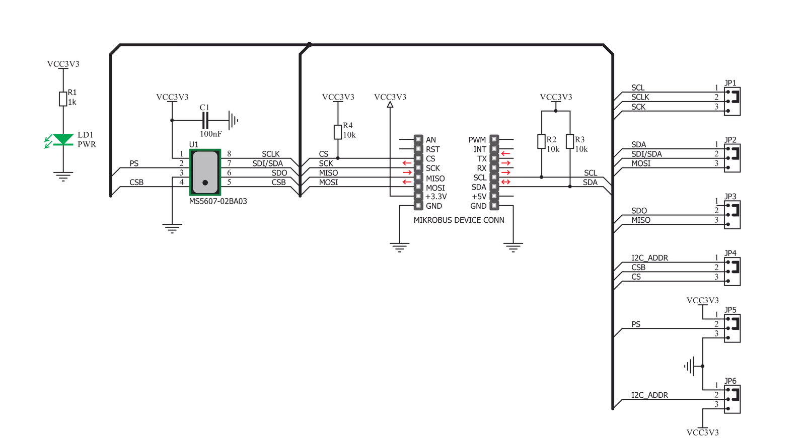
Take a closer look
Click board™ Schematic
Step by step
Project assembly

Start by selecting your development board and Click board™. Begin with the EasyAVR v7 as your development board.


Track your results in real time
Application Output
1. Application Output - In Debug mode, the 'Application Output' window enables real-time data monitoring, offering direct insight into execution results. Ensure proper data display by configuring the environment correctly using the provided tutorial.

2. UART Terminal - Use the UART Terminal to monitor data transmission via a USB to UART converter, allowing direct communication between the Click board™ and your development system. Configure the baud rate and other serial settings according to your project's requirements to ensure proper functionality. For step-by-step setup instructions, refer to the provided tutorial.

3. Plot Output - The Plot feature offers a powerful way to visualize real-time sensor data, enabling trend analysis, debugging, and comparison of multiple data points. To set it up correctly, follow the provided tutorial, which includes a step-by-step example of using the Plot feature to display Click board™ readings. To use the Plot feature in your code, use the function: plot(*insert_graph_name*, variable_name);. This is a general format, and it is up to the user to replace 'insert_graph_name' with the actual graph name and 'variable_name' with the parameter to be displayed.

Software Support
Library Description
This library contains API for Altitude 2 Click driver.
Key functions:
altitude2_read_prom- This function reads calibration data from PROMaltitude2_reset- This function resets the device and reads calibration coefficients after resetaltitude2_read_data- Data read function
Open Source
Code example
The complete application code and a ready-to-use project are available through the NECTO Studio Package Manager for direct installation in the NECTO Studio. The application code can also be found on the MIKROE GitHub account.
/*!
 * \file
 * \brief Altitude2 Click example
 *
 * # Description
 * This demo demonstrates the use of Altitude 2 Click to measure temperature, altitude and pressure.
 *
 * The demo application is composed of two sections :
 *
 * ## Application Init
 * Initializes I2C driver and performs the device reset,
 * after which the calibration coefficients will be read.
 * Determines the ratio value for temperature and pressure measurements.
 * Calibration coefficients are necessary to read after the device reset.
 *
 * ## Application Task
 * Gets temperature data in celsius value and pressure data in mbar value.
 * Gets the calculated altitude value in meters which depends on the temperature and pressure measurements.
 * Logs results on USBUART and repeats operation each second.
 *
 * @note
 * Altitude is dependent from correct outside readings. It's calculated from pressure and temperature readings.
 *
 * \author MikroE Team
 *
 */
// ------------------------------------------------------------------- INCLUDES

#include "board.h"
#include "log.h"
#include "altitude2.h"

// ------------------------------------------------------------------ VARIABLES

static altitude2_t altitude2;
static log_t logger;
float temperature;
float pressure;
float altitude;

// ------------------------------------------------------ APPLICATION FUNCTIONS

void application_init ( void )
{
    log_cfg_t log_cfg;
    altitude2_cfg_t cfg;

    /**
     * Logger initialization.
     * Default baud rate: 115200
     * Default log level: LOG_LEVEL_DEBUG
     * @note If USB_UART_RX and USB_UART_TX
     * are defined as HAL_PIN_NC, you will
     * need to define them manually for log to work.
     * See @b LOG_MAP_USB_UART macro definition for detailed explanation.
     */
    LOG_MAP_USB_UART( log_cfg );
    log_init( &logger, &log_cfg );
    log_info( &logger, "---- Application Init ----" );

    //  Click initialization.

    altitude2_cfg_setup( &cfg );
    ALTITUDE2_MAP_MIKROBUS( cfg, MIKROBUS_1 );
    altitude2_init( &altitude2, &cfg );
    Delay_ms ( 500 );
    altitude2_reset( &altitude2 );

    altitude2_set_ratio ( &altitude2, ALTITUDE2_RATIO_2048, ALTITUDE2_RATIO_2048 );
    log_printf( &logger, "Altitude 2 is initialized\r\n" );
    Delay_ms ( 200 );
}

void application_task ( void )
{
    altitude2_read_data( &altitude2, &temperature, &pressure, &altitude );

    log_printf( &logger, "Temperature: %.2f Celsius\r\n", temperature );
    log_printf( &logger, "Pressure: %.2f mbar\r\n", pressure );
    log_printf( &logger, "Altitude: %.2f m\r\n", altitude );
    log_printf( &logger, "---------------------------------------\r\n\r\n" );

    Delay_ms ( 1000 );
}

int main ( void )
{
    /* Do not remove this line or clock might not be set correctly. */
    #ifdef PREINIT_SUPPORTED
    preinit();
    #endif

    application_init( );

    for ( ; ; )
    {
        application_task( );
    }

    return 0;
}


// ------------------------------------------------------------------------ END


