Make every move an epic adventure with SKRHABE010 and ATmega1284
Play your game, your way

Published Oct 17, 2023
Click board™
Joystick 2 Click
Dev. board
EasyAVR v7
Compiler
NECTO Studio
MCU
ATmega1284
Experience the future of navigation with the smart joystick concept, providing users with a seamless and intuitive way to explore digital worlds
A
A
Hardware Overview
How does it work?
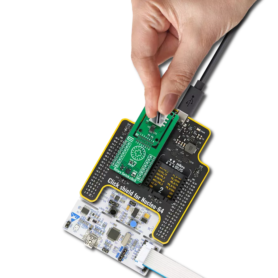
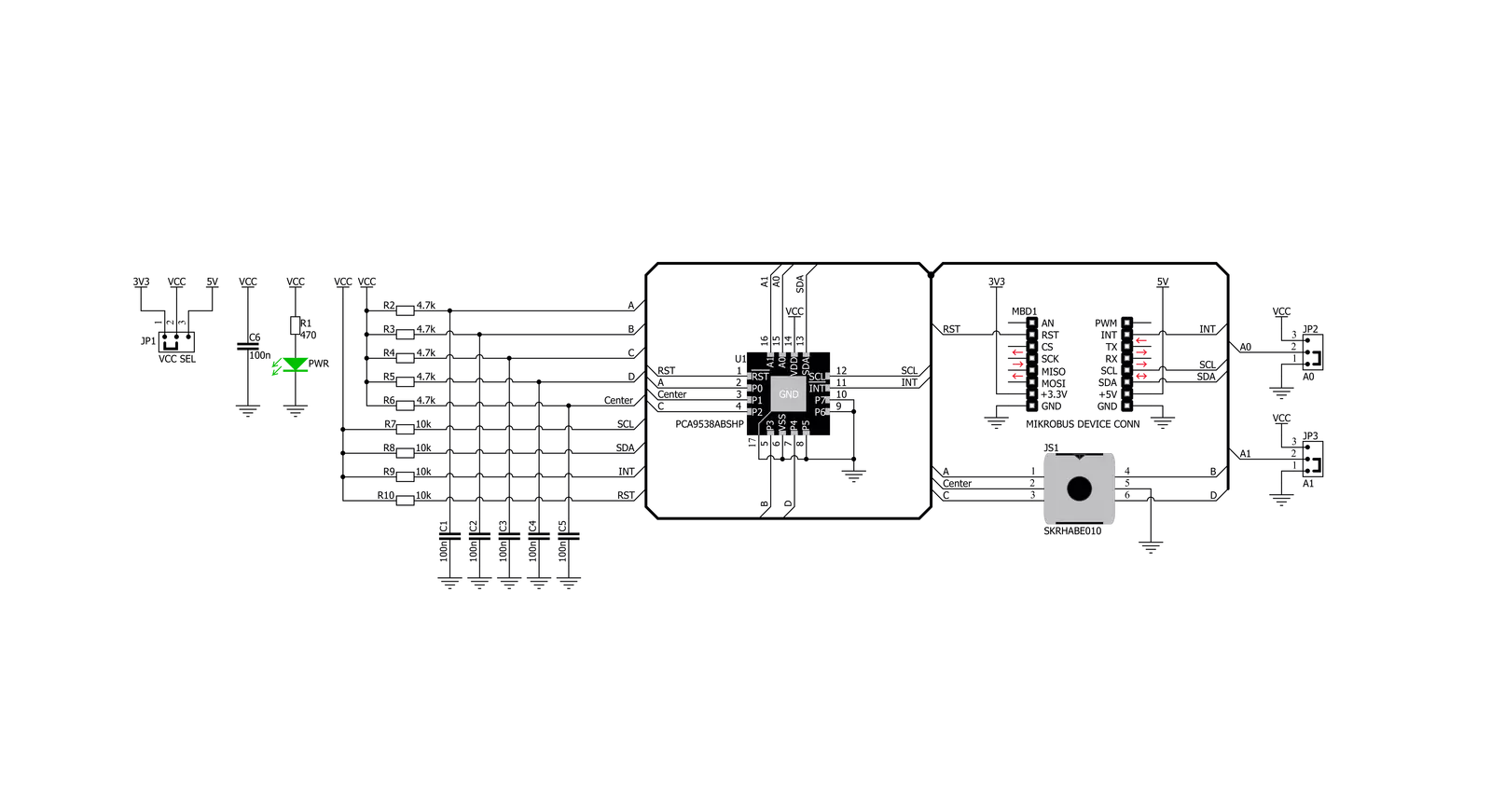
Joystick 2 Click is based on the SKRHABE01, a 4-direction joystick switch with Center-push Function from Alps Alpine. It is positioned on the board so it is easily accessible for interacting and the lever could be pressed, activating the microswitch that way. The microswitch is actuated by applying very little physical force, using a tipping-point mechanism which results in fast and reliable snap-in action. It has both NO (Normal open) contacts routed to the mikroBUS™ over the port expander. The switch lines are equipped with the RC filters, which serve as debouncing
elements for the switch and also to pull-up the lines when they are left afloat. This way, the contact bouncing is reduced even further, resulting in an accurate detection of the switching event. As already mentioned above, this click board™ contains the port expander, relatively large number of needed GPIO pins for the joystick switch. Used IC is PCA9538A, Low-voltage 8-bit I2C-bus I/O port with interrupt and reset, from NXP Semiconductors. It uses the I2C communication for interfacing with the main MCU, which simplifies the number of needed pins,
and therefore the design itself. The Active LOW reset input (RESET) and Open-drain active LOW interrupt output (INT) pins helps simplifying the design even further. This Click board™ can operate with either 3.3V or 5V logic voltage levels selected via the VCC SEL jumper. This way, both 3.3V and 5V capable MCUs can use the communication lines properly. Also, this Click board™ comes equipped with a library containing easy-to-use functions and an example code that can be used as a reference for further development.


Features overview
Development board
EasyAVR v7 is the seventh generation of AVR development boards specially designed for the needs of rapid development of embedded applications. It supports a wide range of 16-bit AVR microcontrollers from Microchip and has a broad set of unique functions, such as a powerful onboard mikroProg programmer and In-Circuit debugger over USB. The development board is well organized and designed so that the end-user has all the necessary elements in one place, such as switches, buttons, indicators, connectors, and others. With four different connectors for each port, EasyAVR v7 allows you to connect accessory boards, sensors, and custom electronics more
efficiently than ever. Each part of the EasyAVR v7 development board contains the components necessary for the most efficient operation of the same board. An integrated mikroProg, a fast USB 2.0 programmer with mikroICD hardware In-Circuit Debugger, offers many valuable programming/debugging options and seamless integration with the Mikroe software environment. Besides it also includes a clean and regulated power supply block for the development board. It can use a wide range of external power sources, including an external 12V power supply, 7-12V AC or 9-15V DC via DC connector/screw terminals, and a power source via the USB Type-B (USB-B)
connector. Communication options such as USB-UART and RS-232 are also included, alongside the well-established mikroBUS™ standard, three display options (7-segment, graphical, and character-based LCD), and several different DIP sockets which cover a wide range of 16-bit AVR MCUs. EasyAVR v7 is an integral part of the Mikroe ecosystem for rapid development. Natively supported by Mikroe software tools, it covers many aspects of prototyping and development thanks to a considerable number of different Click boards™ (over a thousand boards), the number of which is growing every day.

Microcontroller Overview
MCU Card / MCU

Architecture
AVR
MCU Memory (KB)
128
Silicon Vendor
Microchip
Pin count
40
RAM (Bytes)
16384
Used MCU Pins
mikroBUS™ mapper
Take a closer look
Click board™ Schematic
Step by step
Project assembly

Start by selecting your development board and Click board™. Begin with the EasyAVR v7 as your development board.


Track your results in real time
Application Output
1. Application Output - In Debug mode, the 'Application Output' window enables real-time data monitoring, offering direct insight into execution results. Ensure proper data display by configuring the environment correctly using the provided tutorial.

2. UART Terminal - Use the UART Terminal to monitor data transmission via a USB to UART converter, allowing direct communication between the Click board™ and your development system. Configure the baud rate and other serial settings according to your project's requirements to ensure proper functionality. For step-by-step setup instructions, refer to the provided tutorial.

3. Plot Output - The Plot feature offers a powerful way to visualize real-time sensor data, enabling trend analysis, debugging, and comparison of multiple data points. To set it up correctly, follow the provided tutorial, which includes a step-by-step example of using the Plot feature to display Click board™ readings. To use the Plot feature in your code, use the function: plot(*insert_graph_name*, variable_name);. This is a general format, and it is up to the user to replace 'insert_graph_name' with the actual graph name and 'variable_name' with the parameter to be displayed.

Software Support
Library Description
This library contains API for Joystick 2 Click driver.
Key functions:
joystick2_set_cfg_register- Functions for configuration joystickjoystick2_get_position- Functions for get Joystick positionjoystick2_get_interrupt_state- Functions for read interrupt state
Open Source
Code example
The complete application code and a ready-to-use project are available through the NECTO Studio Package Manager for direct installation in the NECTO Studio. The application code can also be found on the MIKROE GitHub account.
/*!
 * \file
 * \brief Joystick2 Click example
 *
 * # Description
 * The demo application shows reading the joistick position ..
 *
 * The demo application is composed of two sections :
 *
 * ## Application Init
 * Configuring Clicks and log objects.
 * Reset device and settings the Click in the default configuration.
 *
 * ## Application Task
 * It reads the position of the joystick,
 * if it detects that the joystick has moved from the zero position,
 * it prints a message about the current position.
 *
 * @note: The I2C peripheral lines external pull up can be required.
 *
 * \author Katarina Perendic
 *
 */
// ------------------------------------------------------------------- INCLUDES

#include "board.h"
#include "log.h"
#include "joystick2.h"

// ------------------------------------------------------------------ VARIABLES

static joystick2_t joystick2;
static log_t logger;

// ------------------------------------------------------ APPLICATION FUNCTIONS

void application_init ( void )
{
    log_cfg_t log_cfg;
    joystick2_cfg_t cfg;

    /**
     * Logger initialization.
     * Default baud rate: 115200
     * Default log level: LOG_LEVEL_DEBUG
     * @note If USB_UART_RX and USB_UART_TX
     * are defined as HAL_PIN_NC, you will
     * need to define them manually for log to work.
     * See @b LOG_MAP_USB_UART macro definition for detailed explanation.
     */
    LOG_MAP_USB_UART( log_cfg );
    log_init( &logger, &log_cfg );
    log_info( &logger, "---- Application Init ----" );

    //  Click initialization.

    joystick2_cfg_setup( &cfg );
    JOYSTICK2_MAP_MIKROBUS( cfg, MIKROBUS_1 );
    joystick2_init( &joystick2, &cfg );

    joystick2_reset( &joystick2 );
    joystick2_default_cfg( &joystick2 );
    log_info( &logger, "---- JOYSTICK START ----" );
}

void application_task ( void )
{
    uint8_t joystick_pos;

    //  Task implementation.

    joystick_pos = joystick2_get_position( &joystick2 );

    switch ( joystick_pos )
    {
        case JOYSTICK2_BUTTON_ACTIVE:
        {
            log_info( &logger, "--- Button is pressed!!! ---" );
            Delay_ms ( 300 );
            break;
        }
        case JOYSTICK2_POSITION_RIGHT:
        {
            log_info( &logger, "--- Joystick position [RIGHT] ---" );
            Delay_ms ( 300 );
            break;
        }
        case JOYSTICK2_POSITION_LEFT:
        {
            log_info( &logger, "--- Joystick position [LEFT] ---" );
            Delay_ms ( 300 );
            break;
        }
        case JOYSTICK2_POSITION_UP:
        {
            log_info( &logger, "--- Joystick position [UP] ---" );
            Delay_ms ( 300 );
            break;
        }
        case JOYSTICK2_POSITION_DOWN:
        {
            log_info( &logger, "--- Joystick position [DOWN] ---" );
            Delay_ms ( 300 );
            break;
        }
    }
}

int main ( void )
{
    /* Do not remove this line or clock might not be set correctly. */
    #ifdef PREINIT_SUPPORTED
    preinit();
    #endif

    application_init( );

    for ( ; ; )
    {
        application_task( );
    }

    return 0;
}


// ------------------------------------------------------------------------ END