Control brushless DC motors in demanding automotive applications with TB9083FTG and ATmega32
Automotive GATE-driver for brushless (BLDC) motor control

Published Sep 05, 2024
Click board™
Brushless 30 Click
Dev. board
EasyAVR v7
Compiler
NECTO Studio
MCU
ATmega32
Take control of your BLDC motors with precision and reliability, ensuring safe performance in even the toughest automotive environments
A
A
Hardware Overview
How does it work?
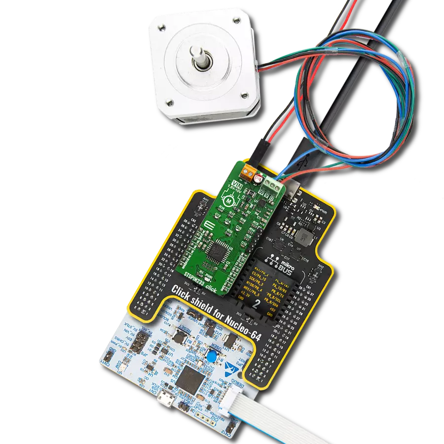
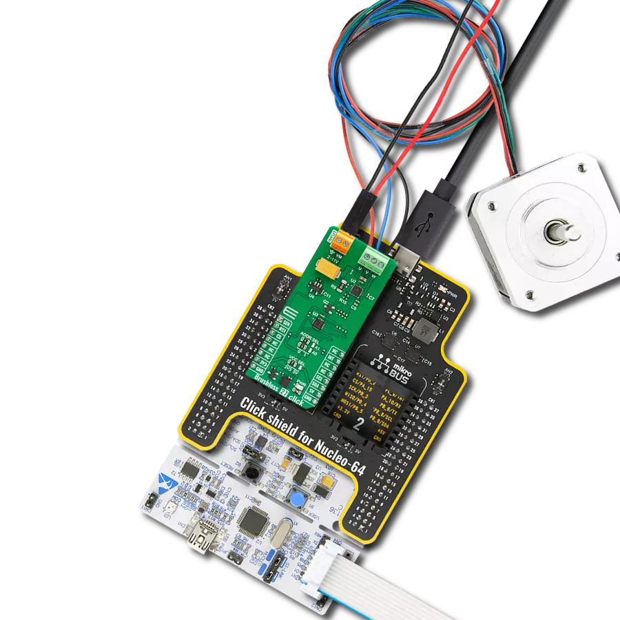
Brushless 30 Click is based on the TB9083FTG, a gate-driver IC from Toshiba Semiconductor, specifically made for automotive environments and qualified under AEC-Q100 and AEC-Q006 standards. This Click board™ leverages the TB9083FTG's capabilities, featuring a three-phase BLDC pre-driver that controls brushless motors through six onboard external MOSFETs (TPH1R104PB). Additionally, it integrates a safety relay pre-driver, ensuring an added layer of protection. The TB9083FTG also incorporates a built-in charge pump, adjustable current sense amplifiers for each motor phase oscillator circuits, and an SPI communication interface, enabling easy configuration and communication with the host MCU. To ensure reliable performance, the TB9083FTG also offers multiple error detection features, including undervoltage, overvoltage, overtemperature, and external MOSFET protection, making Brushless 30 Click a reliable choice for demanding automotive motor control applications such as electric power steering (EPS), powered brakes, and pumps. This Click board™ is designed to support a wide range of external power supplies, accepting input voltages from 4.5V to 28V through
terminals on the board's front side. It can deliver a peak output current of up to 10A, providing robust power for driving BLDC motors connected to the terminals on the bottom side. The board includes dedicated pins via the unpopulated J1 connector for the connection of the 6 PWM signals, provided by the driving device, required to drive the BLDC motor connected to the terminals of the Brushless 30 Click board™. As previously mentioned, Brushless 30 Click communicates with the host MCU through a 4-wire SPI interface, supporting a maximum clock frequency of 2MHz, ensuring fast and reliable data transfer. The SPI interface allows for the modification of settings, such as trigger thresholds and response actions. In addition to the interface pins, the board also uses two other pins on the mikroBUS™ socket. The ALR pin is used to turn ON or OFF the motor drive and the safety pre-driver circuit. i.e. in case an abnormality situation is detected. This pin is connected to a red ALR LED indicator that provides visual alerts for such conditions. Similarly, the DAG pin functions as a diagnostic output of the TB9083FTG, offering information on whether the an error condition has been detected.. This pin is linked to an orange DAG
LED indicator, which visually signals the diagnostic status. Besides the J1 header, this board includes several other unpopulated headers offering additional functionality. The AxO (J3) header is connected to the current detector circuit, which features three motor current detector amplifiers. These outputs can amplify the differential voltage caused by the current passing through the shunt resistor connected to the motor drive, providing precise current measurements. The SRxO (J4) header is linked to the safety relay pre driver, which controls the power or motor relay connected to this unpopulated header. The safety relay pre-driver circuit is managed through the CP_RLY_CTRL SPI register and includes a built-in 500Ω resistor and a backflow prevention diode to protect against reverse connections. This Click board™ can operate with either 3.3V or 5V logic voltage levels selected via the VCC SEL jumper. This way, both 3.3V and 5V capable MCUs can use the communication lines properly. Also, this Click board™ comes equipped with a library containing easy-to-use functions and an example code that can be used as a reference for further development.

Features overview
Development board
EasyAVR v7 is the seventh generation of AVR development boards specially designed for the needs of rapid development of embedded applications. It supports a wide range of 16-bit AVR microcontrollers from Microchip and has a broad set of unique functions, such as a powerful onboard mikroProg programmer and In-Circuit debugger over USB. The development board is well organized and designed so that the end-user has all the necessary elements in one place, such as switches, buttons, indicators, connectors, and others. With four different connectors for each port, EasyAVR v7 allows you to connect accessory boards, sensors, and custom electronics more
efficiently than ever. Each part of the EasyAVR v7 development board contains the components necessary for the most efficient operation of the same board. An integrated mikroProg, a fast USB 2.0 programmer with mikroICD hardware In-Circuit Debugger, offers many valuable programming/debugging options and seamless integration with the Mikroe software environment. Besides it also includes a clean and regulated power supply block for the development board. It can use a wide range of external power sources, including an external 12V power supply, 7-12V AC or 9-15V DC via DC connector/screw terminals, and a power source via the USB Type-B (USB-B)
connector. Communication options such as USB-UART and RS-232 are also included, alongside the well-established mikroBUS™ standard, three display options (7-segment, graphical, and character-based LCD), and several different DIP sockets which cover a wide range of 16-bit AVR MCUs. EasyAVR v7 is an integral part of the Mikroe ecosystem for rapid development. Natively supported by Mikroe software tools, it covers many aspects of prototyping and development thanks to a considerable number of different Click boards™ (over a thousand boards), the number of which is growing every day.

Microcontroller Overview
MCU Card / MCU

Architecture
AVR
MCU Memory (KB)
32
Silicon Vendor
Microchip
Pin count
40
RAM (Bytes)
2048
You complete me!
Accessories
Brushless DC (BLDC) Motor with a Hall sensor represents a high-performance motor from the 42BLF motor series. This motor, wired in a star configuration, boasts a Hall Effect angle of 120°, ensuring precise and reliable performance. With a compact motor length of 47mm and a lightweight design tipping the scales at just 0.29kg, this BLDC motor is engineered to meet your needs. Operating flawlessly at a voltage rating of 24VDC and a speed range of 4000 ± 10% RPM, this motor offers consistent and dependable power. It excels in a normal operational temperature range from -20 to +50°C, maintaining efficiency with a rated current of 1.9A. Also, this product seamlessly integrates with all Brushless Click boards™ and those that require BLDC motors with Hall sensors.

Used MCU Pins
mikroBUS™ mapper
Take a closer look
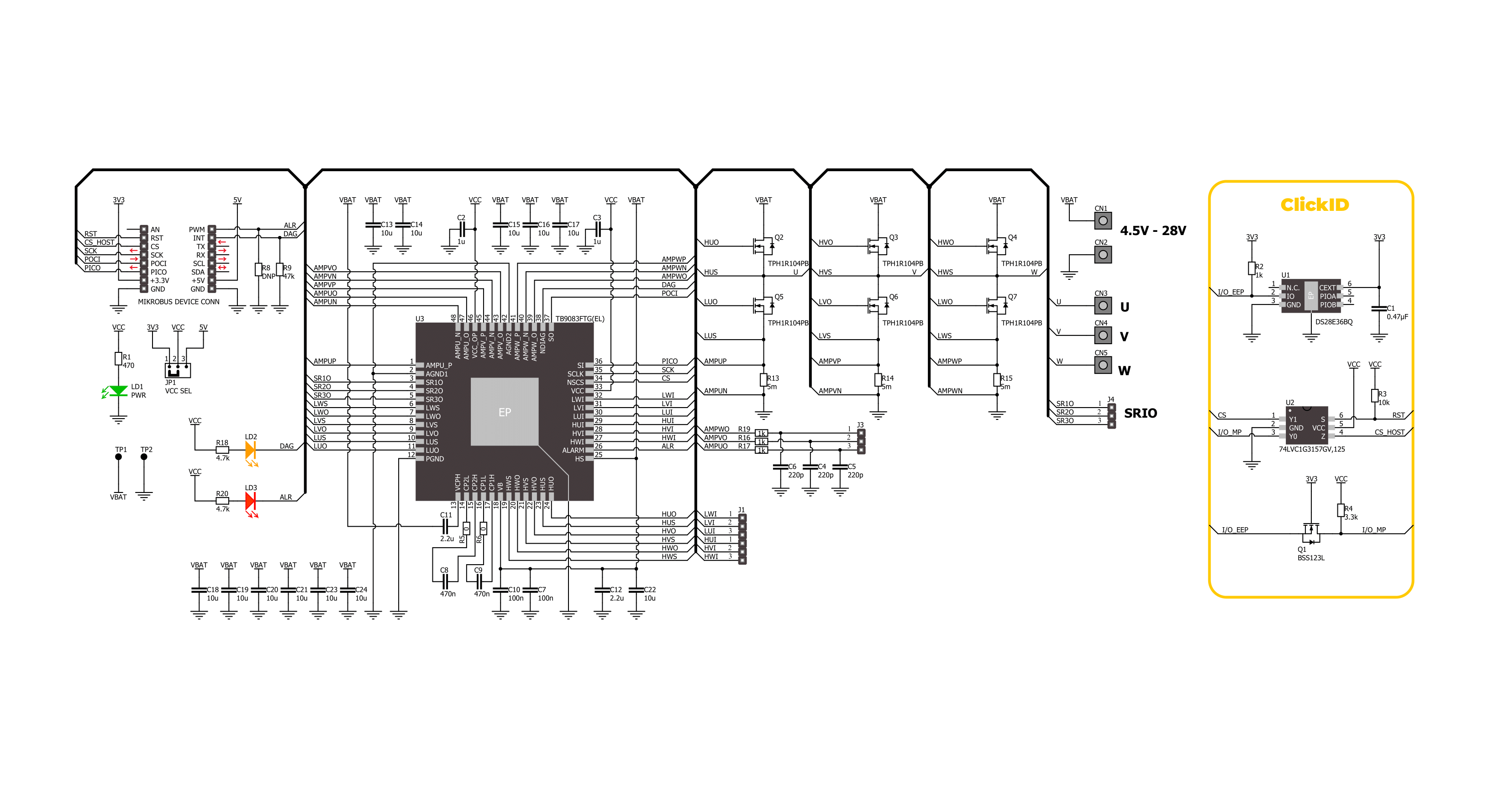
Click board™ Schematic
Step by step
Project assembly

Start by selecting your development board and Click board™. Begin with the EasyAVR v7 as your development board.


Software Support
Library Description
This library contains API for Brushless 30 Click driver.
Key functions:
brushless30_write_reg- This function writes a data word to the selected register by using SPI serial interface.brushless30_read_reg- This function reads a data word from the selected register by using SPI serial interface.brushless30_get_diag_pin- This function returns the DIAG pin logic state.
Open Source
Code example
The complete application code and a ready-to-use project are available through the NECTO Studio Package Manager for direct installation in the NECTO Studio. The application code can also be found on the MIKROE GitHub account.
/*!
 * @file main.c
 * @brief Brushless 30 Click example
 *
 * # Description
 * This example configures the Brushless 30 Click board and makes it ready for
 * the motor control over 6 PWM input signals.
 *
 * The demo application is composed of two sections :
 *
 * ## Application Init
 * Initializes the driver and performs the Click default configuration.
 *
 * ## Application Task
 * Monitors the DIAG pin state, displays the STAT1 and STAT2 registers on the USB UART,
 * and clears the set flags.
 *
 * @author Stefan Filipovic
 *
 */

#include "board.h"
#include "log.h"
#include "brushless30.h"

static brushless30_t brushless30;
static log_t logger;

void application_init ( void )
{
    log_cfg_t log_cfg;  /**< Logger config object. */
    brushless30_cfg_t brushless30_cfg;  /**< Click config object. */

    /**
     * Logger initialization.
     * Default baud rate: 115200
     * Default log level: LOG_LEVEL_DEBUG
     * @note If USB_UART_RX and USB_UART_TX
     * are defined as HAL_PIN_NC, you will
     * need to define them manually for log to work.
     * See @b LOG_MAP_USB_UART macro definition for detailed explanation.
     */
    LOG_MAP_USB_UART( log_cfg );
    log_init( &logger, &log_cfg );
    log_info( &logger, " Application Init " );

    // Click initialization.
    brushless30_cfg_setup( &brushless30_cfg );
    BRUSHLESS30_MAP_MIKROBUS( brushless30_cfg, MIKROBUS_1 );
    if ( SPI_MASTER_ERROR == brushless30_init( &brushless30, &brushless30_cfg ) )
    {
        log_error( &logger, " Communication init." );
        for ( ; ; );
    }

    if ( BRUSHLESS30_ERROR == brushless30_default_cfg ( &brushless30 ) )
    {
        log_error( &logger, " Default configuration." );
        for ( ; ; );
    }

    log_printf( &logger, " Click is configured successfully.\r\n" );
    log_printf( &logger, " Apply a 6 PWM signals to UVW H/L pins to drive the motor.\r\n" );

    log_info( &logger, " Application Task " );
}

void application_task ( void )
{
    uint16_t status = 0;
    if ( !brushless30_get_diag_pin ( &brushless30 ) )
    {
        if ( BRUSHLESS30_OK == brushless30_read_reg ( &brushless30, BRUSHLESS30_REG_STAT1, &status ) )
        {
            if ( status )
            {
                log_printf( &logger, " STAT1: 0x%.4X\r\n", status );
                if ( BRUSHLESS30_OK == brushless30_write_reg ( &brushless30, BRUSHLESS30_REG_STAT1, status ) )
                {
                    log_printf( &logger, " STAT1: cleared\r\n" );
                }
            }
        }

        if ( BRUSHLESS30_OK == brushless30_read_reg ( &brushless30, BRUSHLESS30_REG_STAT2, &status ) )
        {
            if ( status )
            {
                log_printf( &logger, " STAT2: 0x%.4X\r\n", status );
                if ( BRUSHLESS30_OK == brushless30_write_reg ( &brushless30, BRUSHLESS30_REG_STAT2, status ) )
                {
                    log_printf( &logger, " STAT2: cleared\r\n" );
                }
            }
        }

        Delay_ms ( 1000 );
    }
}

int main ( void )
{
    /* Do not remove this line or clock might not be set correctly. */
    #ifdef PREINIT_SUPPORTED
    preinit();
    #endif

    application_init( );

    for ( ; ; )
    {
        application_task( );
    }

    return 0;
}

// ------------------------------------------------------------------------ END
Additional Support
Resources
Category:Brushless