Achieve precise management of brushless DC motors in both industrial and consumer applications with TC78B016FTG and ATmega32
Three-phase sine-wave PWM driver for brushless DC motors

Published Mar 26, 2024
Click board™
Brushless 10 Click
Dev Board
EasyAVR v7
Compiler
NECTO Studio
MCU
ATmega32
Brushless DC motor control ideal for precise speed and direction adjustments in cooling systems, automation, and precision machinery
A
A
Hardware Overview
How does it work?
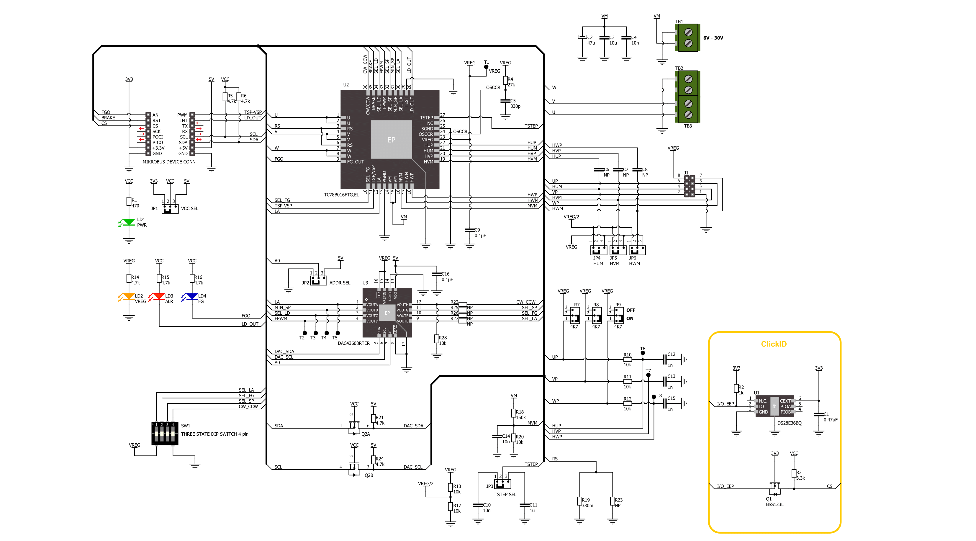
Brushless 10 Click is based on the TC78B016FTG, a 3-phase sine-wave PWM driver for brushless DC motors from Toshiba Semiconductor. This driver is equipped with Toshiba's Intelligent Phase Control (InPAC), an advanced feature designed to automate the motor's phase adjustment. Doing so negates manual calibration, streamlines the setup process, and boosts the motor's efficiency. Primarily utilized in fan motors, this driver leverages its phase adjustment capability to enhance operational efficiency significantly. The TC78B016FTG has several control and diagnostic features to effectively manage and monitor brushless DC motors. The FGO (Rotational Speed Output) function produces a rotation pulse derived from hall sensors, offering a choice between one or three pulses per electrical angle, configurable via an FG switch or an onboard DAC if R26 is populated. This allows for a HIGH logic level (logic 1) to emit three pulses per electrical angle and a LOW logic level (logic 0) for one pulse, visually indicating the operational mode by a blue FG LED. The motor operation can be stopped using the BRK pin, where a HIGH logic state activates the Brake function, and a LOW state resumes Normal operation. Motor speed control is managed through the TSP (Rotational Speed Command) feature, which allows startup, stop, and speed adjustments based on the PWM duty output. This feature is selectable through either analog voltage or pulse duty control, achieved via the SP switch or an onboard DAC if R25 is populated. The LD pin enhances safety by detecting abnormalities such as overcurrent, thermal shutdown, motor lockout, or under/overvoltage conditions, with visual alerts provided by a red ALR LED. Additionally, the board facilitates directional control of the motor, enabling
forward or reverse rotation through the CW/CCW switch or an onboard DAC if R22 is populated, with a LOW level for forward and HIGH for setting reverse direction. The TC78B016FTG's additional functionalities are tunable via the onboard DAC43608, which interfaces with the host MCU through an I2C connection. This DAC enables the selection of its I2C address through the ADDR SEL jumper by setting it to position 0 or 1, thereby offering a layer of customization for the communication protocol. Various motor control enhancements can be implemented through this DAC, like Lead Angle Control. This feature dynamically improves motor efficiency in response to rotation speed and current variations. This control can be activated using the LA switch for Intelligent Phase Control (InPAC) or Proportion to Frequency adjustments or through an external lead angle control, adjustable via input voltage for a range of 0° to 58° when R27 is populated. Additionally, it allows for setting a minimum output duty cycle and the configuration of Motor Lockout, determining whether the lockout function is active and its duration of operation versus pause. Furthermore, the DAC enables the selection of the motor's PWM frequency, offering options of 25kHz, 50kHz, 100kHz, or 200kHz, tailoring the motor's performance to the application's needs. Another key feature of this Click board™ is the TSTEP SEL jumper, which performs the acceleration and deceleration control of the motor. This function allows the motor to gradually increase or decrease its speed at startup, with the timing of these transitions adjustable to either 0.01 or 10 seconds based on the jumper's position. Brushless 10 Click supports an external power supply from 6V to 30V through the VM terminal and allows for current
output adjustments up to 3A, thanks to the R19 and R23 current sense resistors. Based on these populated current sense resistors, which form a value of 150mΩ, the current is rated on 1.5A. This feature ensures that the board can manage various brushless DC (BLDC) motors, including those equipped with Hall sensors, like the BLDC Motor with Hall Sensor offered by MIKROE. In addition to the motor connection terminals, the board is equipped with dedicated pins to connect these additional Hall signals, enhancing the motor's precision and efficiency. Moreover, the board can fine-tune these Hall signal inputs by using optional 4k7 pull-up resistors, which can be added via jumpers on the back of the board. Depending on the user's requirements, these jumpers can be set to an ON or OFF position, offering a layer of customization for signal integrity. Furthermore, this Click board™ is pre-configured for the operational mode of Hall IC usage, with provided additional configuration of Hall U/V/W signals based on a reference voltage provided by the TC78B016FTG. This configuration is set through front-side jumpers to Vreg/2 (2.5V) or Vreg (5V) positions. De-soldering some elements on the board is mandatory in the case of Hall element use. An orange VREG LED visually indicates this reference voltage, ensuring that users can easily verify the board's status at a glance. This Click board™ can operate with either 3.3V or 5V logic voltage levels selected via the VCC SEL jumper. This way, both 3.3V and 5V capable MCUs can use the communication lines properly. Also, this Click board™ comes equipped with a library containing easy-to-use functions and an example code that can be used as a reference for further development.

Features overview
Development board
EasyAVR v7 is the seventh generation of AVR development boards specially designed for the needs of rapid development of embedded applications. It supports a wide range of 16-bit AVR microcontrollers from Microchip and has a broad set of unique functions, such as a powerful onboard mikroProg programmer and In-Circuit debugger over USB. The development board is well organized and designed so that the end-user has all the necessary elements in one place, such as switches, buttons, indicators, connectors, and others. With four different connectors for each port, EasyAVR v7 allows you to connect accessory boards, sensors, and custom electronics more
efficiently than ever. Each part of the EasyAVR v7 development board contains the components necessary for the most efficient operation of the same board. An integrated mikroProg, a fast USB 2.0 programmer with mikroICD hardware In-Circuit Debugger, offers many valuable programming/debugging options and seamless integration with the Mikroe software environment. Besides it also includes a clean and regulated power supply block for the development board. It can use a wide range of external power sources, including an external 12V power supply, 7-12V AC or 9-15V DC via DC connector/screw terminals, and a power source via the USB Type-B (USB-B)
connector. Communication options such as USB-UART and RS-232 are also included, alongside the well-established mikroBUS™ standard, three display options (7-segment, graphical, and character-based LCD), and several different DIP sockets which cover a wide range of 16-bit AVR MCUs. EasyAVR v7 is an integral part of the Mikroe ecosystem for rapid development. Natively supported by Mikroe software tools, it covers many aspects of prototyping and development thanks to a considerable number of different Click boards™ (over a thousand boards), the number of which is growing every day.

Microcontroller Overview
MCU Card / MCU

Architecture
AVR
MCU Memory (KB)
32
Silicon Vendor
Microchip
Pin count
40
RAM (Bytes)
2048
You complete me!
Accessories
Brushless DC (BLDC) Motor with a Hall sensor represents a high-performance motor from the 42BLF motor series. This motor, wired in a star configuration, boasts a Hall Effect angle of 120°, ensuring precise and reliable performance. With a compact motor length of 47mm and a lightweight design tipping the scales at just 0.29kg, this BLDC motor is engineered to meet your needs. Operating flawlessly at a voltage rating of 24VDC and a speed range of 4000 ± 10% RPM, this motor offers consistent and dependable power. It excels in a normal operational temperature range from -20 to +50°C, maintaining efficiency with a rated current of 1.9A. Also, this product seamlessly integrates with all Brushless Click boards™ and those that require BLDC motors with Hall sensors.

Used MCU Pins
mikroBUS™ mapper
Take a closer look
Click board™ Schematic
Step by step
Project assembly

Start by selecting your development board and Click board™. Begin with the EasyAVR v7 as your development board.


Track your results in real time
Application Output
1. Application Output - In Debug mode, the 'Application Output' window enables real-time data monitoring, offering direct insight into execution results. Ensure proper data display by configuring the environment correctly using the provided tutorial.

2. UART Terminal - Use the UART Terminal to monitor data transmission via a USB to UART converter, allowing direct communication between the Click board™ and your development system. Configure the baud rate and other serial settings according to your project's requirements to ensure proper functionality. For step-by-step setup instructions, refer to the provided tutorial.

3. Plot Output - The Plot feature offers a powerful way to visualize real-time sensor data, enabling trend analysis, debugging, and comparison of multiple data points. To set it up correctly, follow the provided tutorial, which includes a step-by-step example of using the Plot feature to display Click board™ readings. To use the Plot feature in your code, use the function: plot(*insert_graph_name*, variable_name);. This is a general format, and it is up to the user to replace 'insert_graph_name' with the actual graph name and 'variable_name' with the parameter to be displayed.

Software Support
Library Description
This library contains API for Brushless 10 Click driver.
Key functions:
brushless10_set_duty_cycle- This function sets the PWM duty cycle in percentages ( Range[ 0..1 ] )brushless10_pull_brake- This function pulls brake by setting the BRAKE pin to high logic statebrushless10_release_brake- This function releases brake by setting the BRAKE pin to low logic state
Open Source
Code example
The complete application code and a ready-to-use project are available through the NECTO Studio Package Manager for direct installation in the NECTO Studio. The application code can also be found on the MIKROE GitHub account.
/*!
 * @file main.c
 * @brief Brushless 10 Click example
 *
 * # Description
 * This example demonstrates the use of the Brushless 10 click board by driving the
 * motor at different speeds.
 *
 * The demo application is composed of two sections :
 *
 * ## Application Init
 * Initializes the driver and performs the click default configuration.
 *
 * ## Application Task
 * Controls the motor speed by changing the PWM duty cycle every 2 seconds.
 * The duty cycle ranges from 20% to 100%. Each step will be logged on the USB UART
 * where you can track the program flow.
 *
 * @author Stefan Filipovic
 *
 */

#include "board.h"
#include "log.h"
#include "brushless10.h"

static brushless10_t brushless10;
static log_t logger;

void application_init ( void )
{
    log_cfg_t log_cfg;  /**< Logger config object. */
    brushless10_cfg_t brushless10_cfg;  /**< Click config object. */

    /**
     * Logger initialization.
     * Default baud rate: 115200
     * Default log level: LOG_LEVEL_DEBUG
     * @note If USB_UART_RX and USB_UART_TX
     * are defined as HAL_PIN_NC, you will
     * need to define them manually for log to work.
     * See @b LOG_MAP_USB_UART macro definition for detailed explanation.
     */
    LOG_MAP_USB_UART( log_cfg );
    log_init( &logger, &log_cfg );
    log_info( &logger, " Application Init " );

    // Click initialization.
    brushless10_cfg_setup( &brushless10_cfg );
    BRUSHLESS10_MAP_MIKROBUS( brushless10_cfg, MIKROBUS_1 );
    if ( BRUSHLESS10_OK != brushless10_init( &brushless10, &brushless10_cfg ) )
    {
        log_error( &logger, " Communication init." );
        for ( ; ; );
    }

    if ( BRUSHLESS10_OK != brushless10_default_cfg ( &brushless10 ) )
    {
        log_error( &logger, " Default configuration." );
        for ( ; ; );
    }

    log_info( &logger, " Application Task " );
}

void application_task ( void )
{
    static int8_t duty_cnt = 2;
    static int8_t duty_inc = 1;
    float duty = duty_cnt / 10.0;

    brushless10_set_duty_cycle ( &brushless10, duty );
    log_printf( &logger, "> Duty: %d%%\r\n", ( uint16_t )( duty_cnt * 10 ) );

    Delay_ms( 2000 );

    duty_cnt += duty_inc;
    if ( duty_cnt > 10 )
    {
        duty_cnt = 9;
        duty_inc = -1;
    }
    else if ( duty_cnt < 2 )
    {
        duty_cnt = 2;
        duty_inc = 1;
        log_printf( &logger, " Pull brake\r\n" );
        brushless10_pull_brake ( &brushless10 );
        Delay_ms( 3000 );
        log_printf( &logger, " Release brake\r\n" );
        brushless10_release_brake ( &brushless10 );
        Delay_ms( 1000 );
    }
}

int main ( void )
{
    application_init( );

    for ( ; ; )
    {
        application_task( );
    }

    return 0;
}

// ------------------------------------------------------------------------ END


