Unlock the art of custom motor control with MP6519 and STM32F415RG
Smooth control for powerful motors
Published Jul 23, 2023
Click board™
H-Bridge 8 Click
Dev. board
STM32 M4 clicker
Compiler
NECTO Studio
MCU
STM32F415RG
Experience unparalleled accuracy and rapid DC motor/solenoid control in applications with our cutting-edge monolithic step-down current-source driver
A
A
Hardware Overview
How does it work?
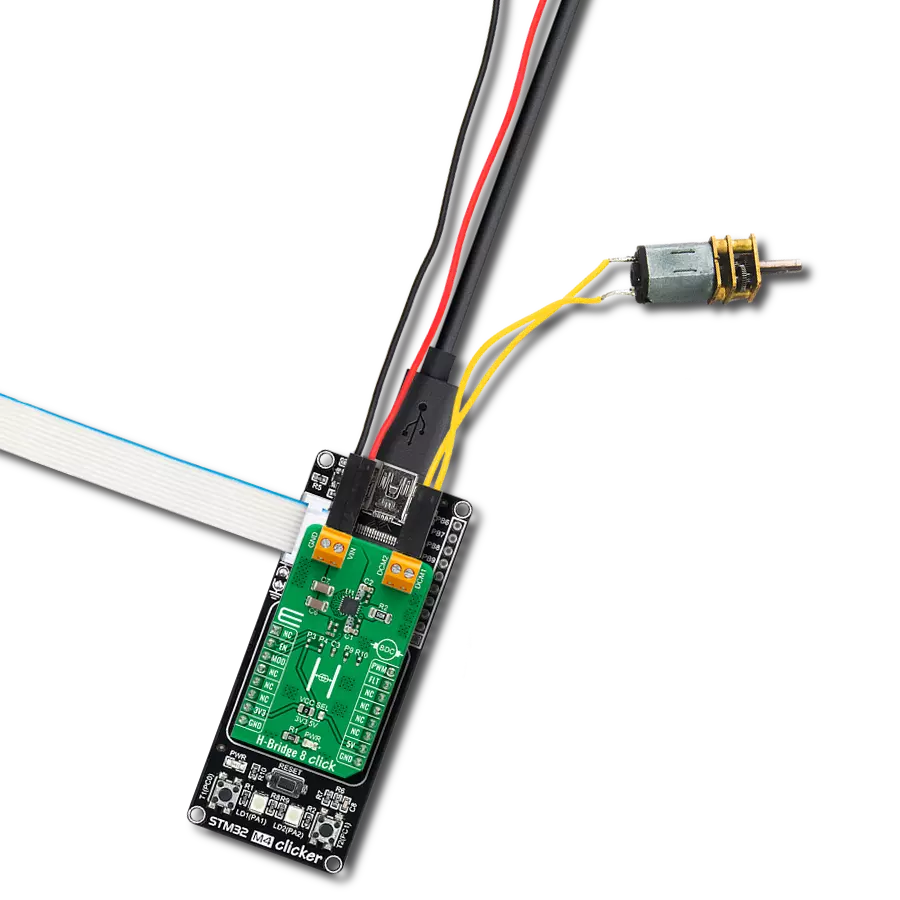
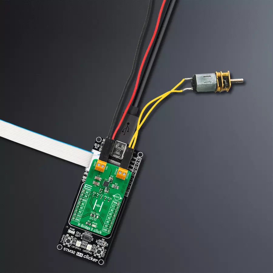
H-Bridge 8 Click is based on the MP6519, a monolithic current-source driver for applications that require accurate and fast current-response control from Monolithic Power Systems (MPS). The MP6519 works in step-down mode with four fully integrated MOSFET H-bridges to provide small size and high efficiency and uses pulse-width-modulation (PWM) signal with average current control to achieve a bidirectional current output and fast dynamic current response. It also has current polarity controlled by a GPIO pin alongside the programmable switching frequency from 30kHz to 300kHz. This Click board™ communicates with MCU using several GPIO pins. The Enable pin, labeled EN and routed to the RST pin of the mikroBUS™ socket, optimizes power consumption and is used for power ON/OFF purposes (driver operation permission).
Also, the Forward/Reverse mode or current direction flowing can be selected according to a logic level of the control signal routed to the CS pin of the mikroBUS™ socket, marked as MOD. In addition, the H-Bridge 8 Click also has a fault pin labeled as FLT routed to the INT pin of the mikroBUS™ socket, indicating the external system's fault condition if any fault occurs during operation. The MP6519 can enter four modes to control the working sequence: Shutdown, Standby, Normal Switching, and Current Polarity Mode. In Shutdown mode, all circuits and blocks are disabled, and the MP6519 consumes less than 1μA. Standby is an initial mode in which control blocks begin working except for the gate drive block for the internal switching MOSFETs. Normal Switching mode activates when both PWM and EN pins are at high logic state (active), while the
MOD pin sets the Current Polarity mode and determines the polarity of the current, more precisely, the direction of rotation of the motor. The H-Bridge 8 Click supports an external power supply for the MP6519, which can be connected to the input terminal labeled as VIN and should be within the range of 2.5V to 28V, while the DC motor coils can be connected to the terminals labeled as DCM1 and DCM2. This Click board™ can operate with either 3.3V or 5V logic voltage levels selected via the VCC SEL jumper. This way, both 3.3V and 5V capable MCUs can use the communication lines properly. However, the Click board™ comes equipped with a library containing easy-to-use functions and an example code that can be used, as a reference, for further development.

Features overview
Development board
STM32 M4 Clicker is a compact starter development board that brings the flexibility of add-on Click boards™ to your favorite microcontroller, making it a perfect starter kit for implementing your ideas. It comes with an onboard 32-bit ARM Cortex-M4 microcontroller, the STM32F415RG from STMicroelectronics, a USB connector, LED indicators, buttons, a JTAG connector, and a header for interfacing with external electronics. Thanks to its compact design with clear and easy-recognizable silkscreen markings, it provides a fluid and immersive working experience, allowing
access anywhere and under any circumstances. Each part of the STM32 M4 Clicker development kit contains the components necessary for the most efficient operation of the same board. In addition to the possibility of choosing the STM32 M4 Clicker programming method, using USB HID mikroBootloader, or through an external mikroProg connector for the STM32 programmer, the Clicker board also includes a clean and regulated power supply module for the development kit. The USB Mini-B connection can provide up to 500mA of current, which is more than enough to operate all
onboard and additional modules. All communication methods that mikroBUS™ itself supports are on this board, including the well-established mikroBUS™ socket, reset button, and several buttons and LED indicators. STM32 M4 Clicker is an integral part of the Mikroe ecosystem, allowing you to create a new application in minutes. Natively supported by Mikroe software tools, it covers many aspects of prototyping thanks to a considerable number of different Click boards™ (over a thousand boards), the number of which is growing every day.

Microcontroller Overview
MCU Card / MCU
Architecture
ARM Cortex-M4
MCU Memory (KB)
1024
Silicon Vendor
STMicroelectronics
Pin count
64
RAM (Bytes)
196608
You complete me!
Accessories
DC Gear Motor - 430RPM (3-6V) represents an all-in-one combination of a motor and gearbox, where the addition of gear leads to a reduction of motor speed while increasing the torque output. This gear motor has a spur gearbox, making it a highly reliable solution for applications with lower torque and speed requirements. The most critical parameters for gear motors are speed, torque, and efficiency, which are, in this case, 520RPM with no load and 430RPM at maximum efficiency, alongside a current of 60mA and a torque of 50g.cm. Rated for a 3-6V operational voltage range and clockwise/counterclockwise rotation direction, this motor represents an excellent solution for many functions initially performed by brushed DC motors in robotics, medical equipment, electric door locks, and much more.

Used MCU Pins
mikroBUS™ mapper
Take a closer look
Click board™ Schematic

Step by step
Project assembly

Start by selecting your development board and Click board™. Begin with the STM32 M4 clicker as your development board.


Track your results in real time
Application Output
1. Application Output - In Debug mode, the 'Application Output' window enables real-time data monitoring, offering direct insight into execution results. Ensure proper data display by configuring the environment correctly using the provided tutorial.

2. UART Terminal - Use the UART Terminal to monitor data transmission via a USB to UART converter, allowing direct communication between the Click board™ and your development system. Configure the baud rate and other serial settings according to your project's requirements to ensure proper functionality. For step-by-step setup instructions, refer to the provided tutorial.

3. Plot Output - The Plot feature offers a powerful way to visualize real-time sensor data, enabling trend analysis, debugging, and comparison of multiple data points. To set it up correctly, follow the provided tutorial, which includes a step-by-step example of using the Plot feature to display Click board™ readings. To use the Plot feature in your code, use the function: plot(*insert_graph_name*, variable_name);. This is a general format, and it is up to the user to replace 'insert_graph_name' with the actual graph name and 'variable_name' with the parameter to be displayed.

Software Support
Library Description
This library contains API for H-Bridge 8 Click driver.
Key functions:
hbridge8_set_mode- H-Bridge 8 set operating mode functionhbridge8_enable- H-Bridge 8 set IC enable functionhbridge8_set_duty_cycle- H-Bridge 8 sets PWM duty cycle
Open Source
Code example
The complete application code and a ready-to-use project are available through the NECTO Studio Package Manager for direct installation in the NECTO Studio. The application code can also be found on the MIKROE GitHub account.
/*!
 * @file main.c
 * @brief HBridge8 Click example
 *
 * # Description
 * This library contains an API for the H-Bridge 8 Click driver.
 * This demo application shows the use of a H-Bridge 8 Click board™.
 *
 * The demo application is composed of two sections :
 *
 * ## Application Init
 * Initialization of PWM module and log UART.
 * After driver initialization, the app set duty cycle, start PWM and
 * set motor drive the forward.
 *
 * ## Application Task
 * This is an example that shows the use of an H-Bridge 8 Click board™.
 * In this example, the app drives the motor forward and switched the PWM signal back and forth
 * from 3% duty cycle to 8% duty cycle and back every 3000 milliseconds.
 * Results are being sent to the Usart Terminal where you can track their changes.
 *
 * @author Nenad Filipovic
 *
 */

#include "board.h"
#include "log.h"
#include "hbridge8.h"

static hbridge8_t hbridge8;
static log_t logger;
uint8_t mode;

void application_init ( void )
{
    log_cfg_t log_cfg;            /**< Logger config object. */
    hbridge8_cfg_t hbridge8_cfg;  /**< Click config object. */

    /**
     * Logger initialization.
     * Default baud rate: 115200
     * Default log level: LOG_LEVEL_DEBUG
     * @note If USB_UART_RX and USB_UART_TX
     * are defined as HAL_PIN_NC, you will
     * need to define them manually for log to work.
     * See @b LOG_MAP_USB_UART macro definition for detailed explanation.
     */
    LOG_MAP_USB_UART( log_cfg );
    log_init( &logger, &log_cfg );
    log_info( &logger, " Application Init " );

    // Click initialization.

    hbridge8_cfg_setup( &hbridge8_cfg );
    HBRIDGE8_MAP_MIKROBUS( hbridge8_cfg, MIKROBUS_1 );
    err_t init_flag  = hbridge8_init( &hbridge8, &hbridge8_cfg );
    if ( PWM_ERROR == init_flag )
    {
        log_error( &logger, " Application Init Error. " );
        log_info( &logger, " Please, run program again... " );

        for ( ; ; );
    }

    hbridge8_default_cfg ( &hbridge8 );
    Delay_ms ( 100 );

    hbridge8_set_mode( &hbridge8, HBRIDGE8_MODE_FORWARD );
    log_printf( &logger, "\r\n>>> Forward\r\n\r\n" );
    hbridge8_set_duty_cycle ( &hbridge8, 0.1 );
    hbridge8_pwm_start( &hbridge8 );
    Delay_ms ( 100 );
}

void application_task ( void )
{
    static int8_t duty_cnt = 3;
    static int8_t duty_inc = 1;
    float duty = duty_cnt / 100.0;

    hbridge8_set_duty_cycle ( &hbridge8, duty );
    log_printf( &logger, "> Duty: %d%%\r\n", ( uint16_t )( duty_cnt ) );

    Delay_ms ( 1000 );
    Delay_ms ( 1000 );
    Delay_ms ( 1000 );

    if ( 8 == duty_cnt )
    {
        duty_inc = -1;
    }
    else if ( 3 == duty_cnt )
    {
        duty_inc = 1;
    }
    duty_cnt += duty_inc;
}

int main ( void )
{
    /* Do not remove this line or clock might not be set correctly. */
    #ifdef PREINIT_SUPPORTED
    preinit();
    #endif

    application_init( );

    for ( ; ; )
    {
        application_task( );
    }

    return 0;
}

// ------------------------------------------------------------------------ END


