Measure acceleration in three axes (X, Y, Z) to detect vibrations and shocks with 830M1-0025 and PIC32MX470F512H
Triaxial piezoelectric accelerometer for vibration and motion monitoring up to ±25g
Published Nov 27, 2024
Click board™
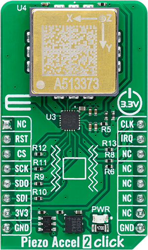
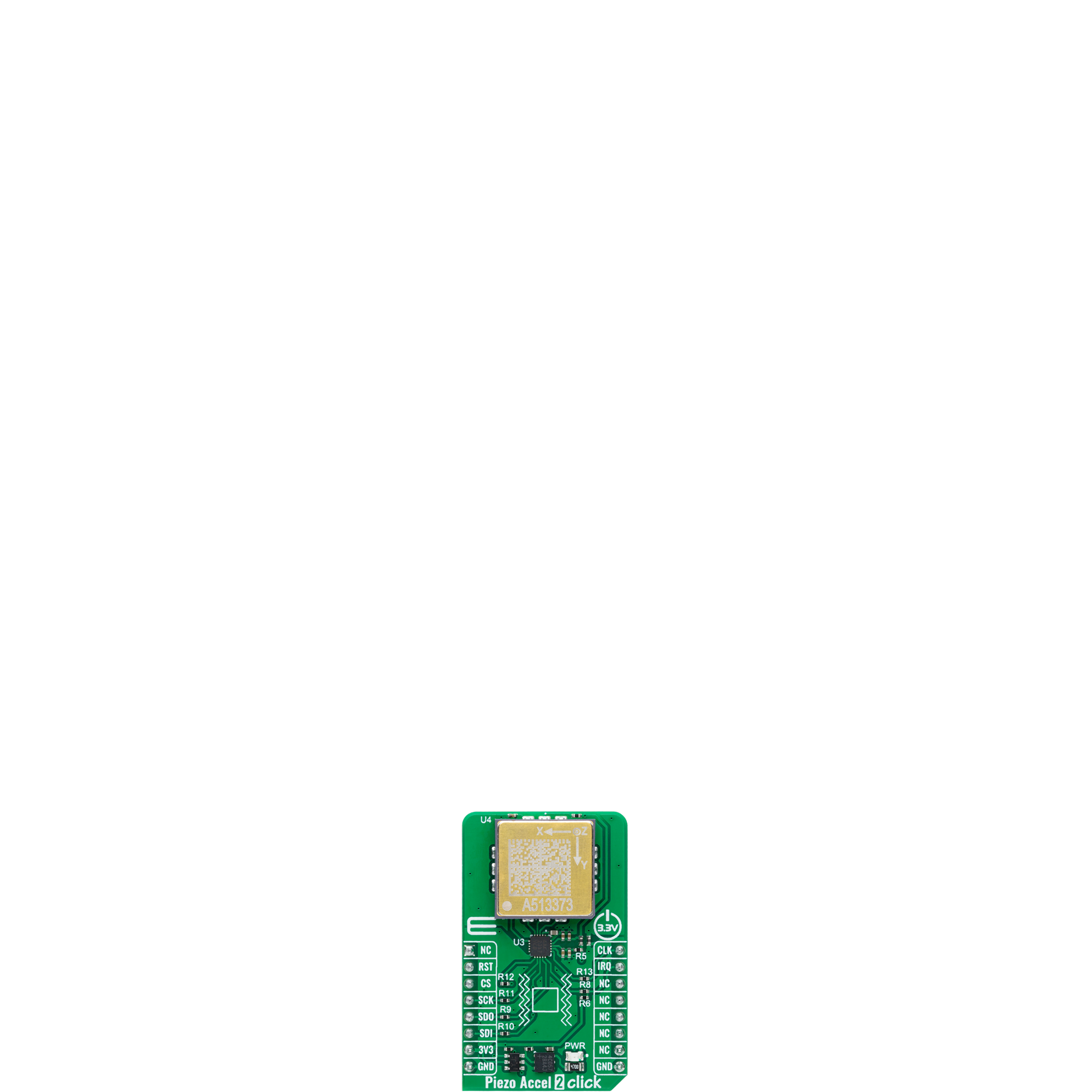
Piezo Accel 2 Click - 25g
Dev. board
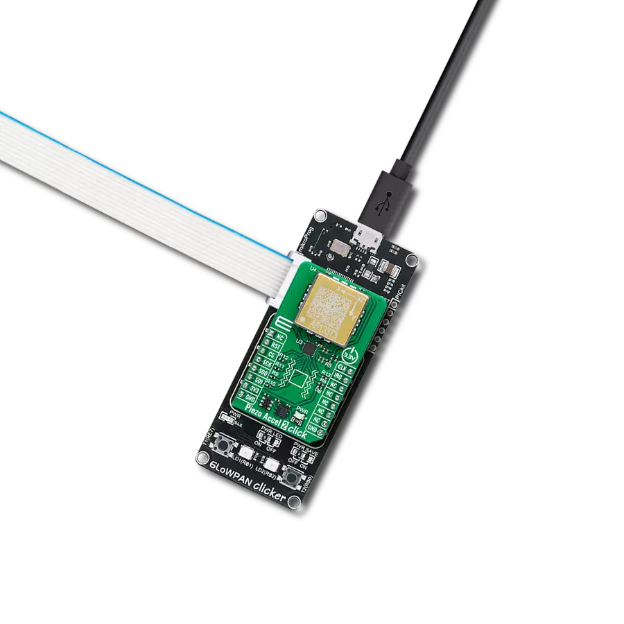
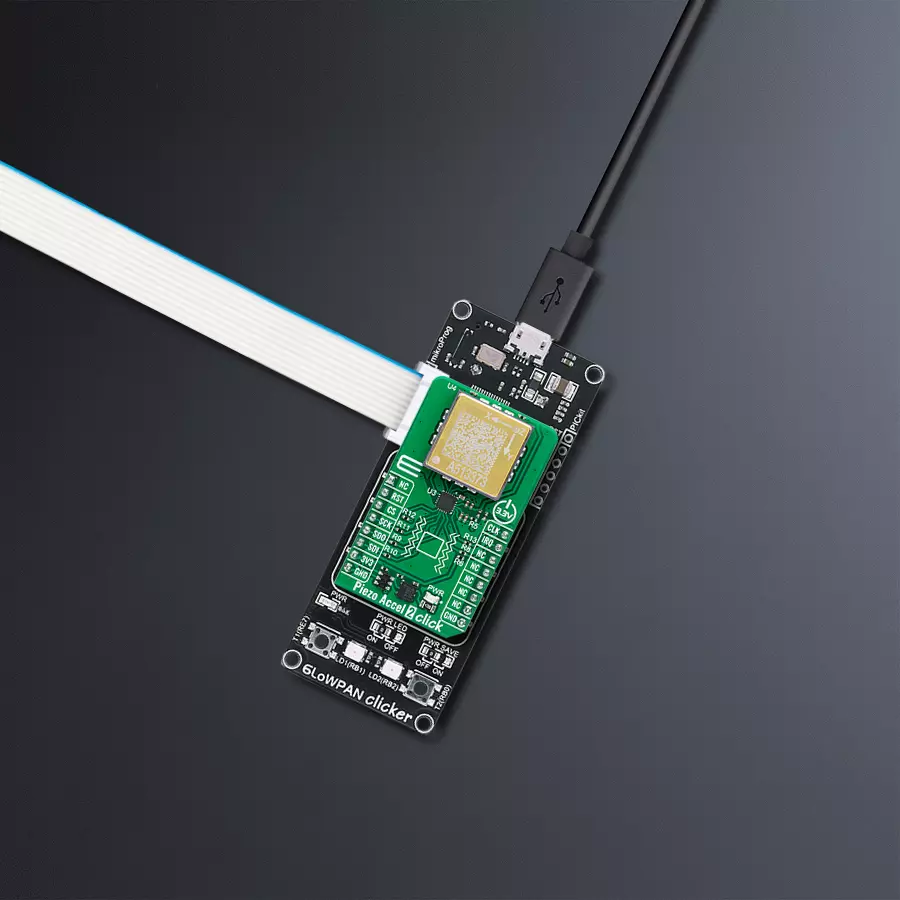
6LoWPAN clicker
Compiler
NECTO Studio
MCU
PIC32MX470F512H
Monitor vibration and motion with precision and temperature sensing, ideal for predictive maintenance and machine health monitoring
A
A
Hardware Overview
How does it work?
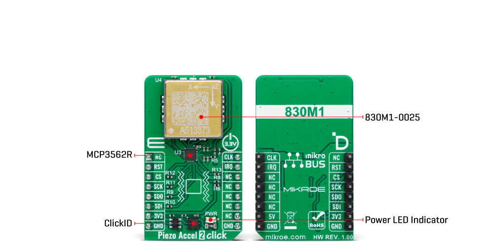
Piezo Accel 2 Click - 25g is based on the 830M1-0025, a triaxial piezoelectric accelerometer from TE Connectivity, capable of detecting motion and acceleration along all three orthogonal axes (X, Y, Z). The 830M1-0025 provides accurate and stable motion and acceleration measurements. It offers analog voltage outputs proportional to the magnitude of acceleration along the X, Y, and Z axes, with a range of ±25g and a sensitivity of 50mV/g. This sensor leverages proven piezoelectric technology for exceptional resolution, dynamic range, and bandwidth, outperforming traditional MEMS devices in demanding environments. Additionally, it features an integrated RTD temperature sensor, enabling simultaneous vibration and temperature data acquisition for comprehensive condition monitoring. Its high sensitivity, reliable performance, and compatibility
with embedded systems make it ideal for applications like machine health monitoring, predictive maintenance, impact and shock monitoring, and security systems. Piezo Accel 2 Click communicates with a host MCU through the onboard MCP3562R, a 24-bit low-noise delta-sigma Analog-to-Digital Converter (ADC). This ADC digitizes the analog outputs from the 830M1-0025 sensor, providing high-resolution data with a programmable data rate of up to 153.6kSPS. The MCP3562R features an internal voltage reference, oscillator, temperature sensor, and burnout sensor detection, further enhancing its functionality. Communication with the host MCU is made via the SPI interface, operating at a maximum frequency of 20MHz. In addition to the SPI communication pins, the MCP3562R also uses CLK and IRQ pins. The CLK pin functions as either a master clock input or
an analog master clock output, depending on the configuration of the ADC’s CONFIG register. This clock is distinct from the SPI clock and is essential for continuous ADC operation during signal conversion. The IRQ pin serves as an interrupt output for various ADC events, such as conversion start, data readiness, power-on reset (POR), and CRC errors in the register map configuration. Furthermore, this pin can also function as a modulator data output, providing synchronized output with the analog master clock. This Click board™ can be operated only with a 3.3V logic voltage level. The board must perform appropriate logic voltage level conversion before using MCUs with different logic levels. Also, it comes equipped with a library containing functions and an example code that can be used as a reference for further development.
Features overview
Development board
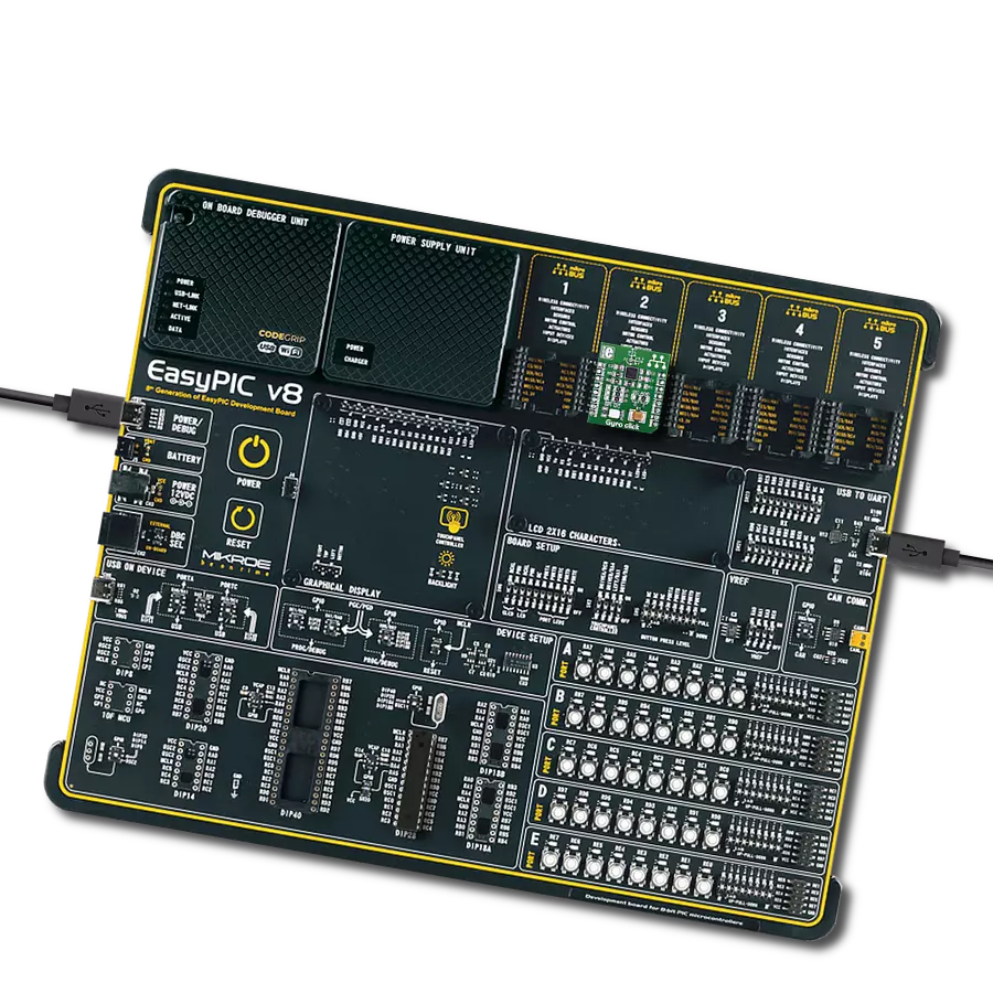
6LoWPAN Clicker is a compact starter development board that brings the flexibility of add-on Click boards™ to your favorite microcontroller, making it a perfect starter kit for implementing your ideas. It comes with an onboard 32-bit PIC microcontroller, the PIC32MX470F512H from Microchip, a USB connector, LED indicators, buttons, a mikroProg connector, and a header for interfacing with external electronics. Along with this microcontroller, the board also contains a 2.4GHz ISM band transceiver, allowing you to add wireless communication to your target application. Its compact design provides a fluid and immersive working experience, allowing access anywhere
and under any circumstances. Each part of the 6LoWPAN Clicker development kit contains the components necessary for the most efficient operation of the same board. In addition to the possibility of choosing the 6LoWPAN Clicker programming method, using USB HID mikroBootloader, or through an external mikroProg connector for PIC, dsPIC, or PIC32 programmer, the Clicker board also includes a clean and regulated power supply module for the development kit. The USB Micro-B connection can provide up to 500mA of current for the Clicker board, which is more than enough to operate all onboard and additional modules, or it can power
over two standard AA batteries. All communication methods that mikroBUS™ itself supports are on this board, including the well-established mikroBUS™ socket, reset button, and several buttons and LED indicators. 6LoWPAN Clicker is an integral part of the Mikroe ecosystem, allowing you to create a new application in minutes. Natively supported by Mikroe software tools, it covers many aspects of prototyping thanks to a considerable number of different Click boards™ (over a thousand boards), the number of which is growing every day.

Microcontroller Overview
MCU Card / MCU

Architecture
PIC32
MCU Memory (KB)
512
Silicon Vendor
Microchip
Pin count
64
RAM (Bytes)
131072
Used MCU Pins
mikroBUS™ mapper
Take a closer look
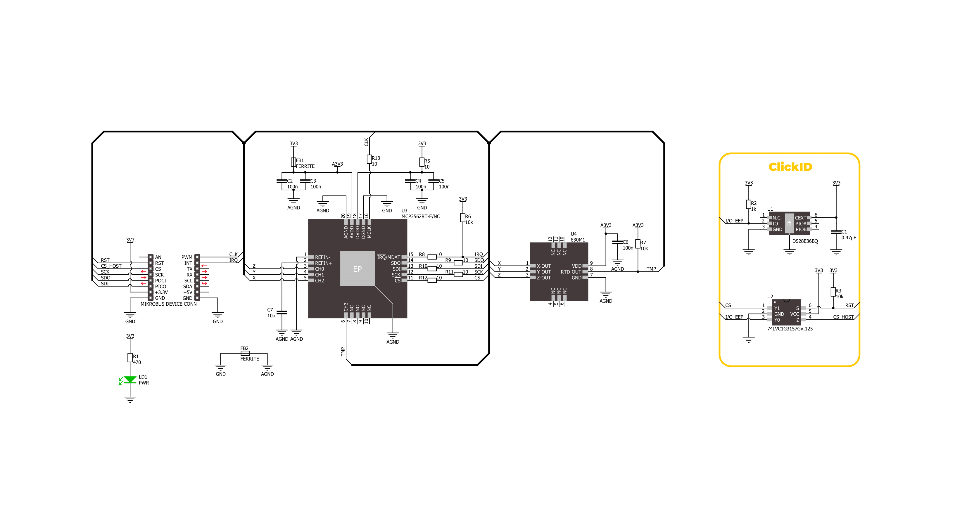
Click board™ Schematic
Step by step
Project assembly

Start by selecting your development board and Click board™. Begin with the 6LoWPAN clicker as your development board.


Track your results in real time
Application Output
1. Application Output - In Debug mode, the 'Application Output' window enables real-time data monitoring, offering direct insight into execution results. Ensure proper data display by configuring the environment correctly using the provided tutorial.

2. UART Terminal - Use the UART Terminal to monitor data transmission via a USB to UART converter, allowing direct communication between the Click board™ and your development system. Configure the baud rate and other serial settings according to your project's requirements to ensure proper functionality. For step-by-step setup instructions, refer to the provided tutorial.

3. Plot Output - The Plot feature offers a powerful way to visualize real-time sensor data, enabling trend analysis, debugging, and comparison of multiple data points. To set it up correctly, follow the provided tutorial, which includes a step-by-step example of using the Plot feature to display Click board™ readings. To use the Plot feature in your code, use the function: plot(*insert_graph_name*, variable_name);. This is a general format, and it is up to the user to replace 'insert_graph_name' with the actual graph name and 'variable_name' with the parameter to be displayed.

Software Support
Library Description
This library contains API for Piezo Accel 2 Click - 25g driver.
Key functions:
piezoaccel225g_read_adc_data- This function reads raw ADC values of X, Y, and Z axis, and the internal temperature sensor measurements.piezoaccel225g_fast_cmd_write- This function writes the selected fast command by using SPI serial interface.piezoaccel225g_reg_read_multi- This function reads a desired number of data bytes starting from the selected register by using SPI serial interface.
Open Source
Code example
The complete application code and a ready-to-use project are available through the NECTO Studio Package Manager for direct installation in the NECTO Studio. The application code can also be found on the MIKROE GitHub account.
/*!
 * @file main.c
 * @brief Piezo Accel 2 25g Click example
 *
 * # Description
 * This example demonstrates the use of Piezo Accel 2 25g Click board by reading and displaying
 * the ADC values of X, Y, and Z axis, and the internal temperature sensor measurements.
 * Those data can be visualized on the SerialPlot application.
 *
 * The demo application is composed of two sections :
 *
 * ## Application Init
 * Initializes the driver and performs the Click default configuration for ADC measurements.
 *
 * ## Application Task
 * Reads the ADC values of X, Y, and Z axis, and the internal temperature sensor measurements
 * and displays them on the USB UART (SerialPlot) every 5ms approximately.
 *
 * @note
 * We recommend using the SerialPlot tool for data visualization. The temperature measurements
 * should be visualized independently. The data format for plotter is as follows: X;Y;Z;TEMP;
 *
 * @author Stefan Filipovic
 *
 */

#include "board.h"
#include "log.h"
#include "piezoaccel225g.h"

static piezoaccel225g_t piezoaccel225g;
static log_t logger;

void application_init ( void )
{
    log_cfg_t log_cfg;  /**< Logger config object. */
    piezoaccel225g_cfg_t piezoaccel225g_cfg;  /**< Click config object. */

    /**
     * Logger initialization.
     * Default baud rate: 115200
     * Default log level: LOG_LEVEL_DEBUG
     * @note If USB_UART_RX and USB_UART_TX
     * are defined as HAL_PIN_NC, you will
     * need to define them manually for log to work.
     * See @b LOG_MAP_USB_UART macro definition for detailed explanation.
     */
    LOG_MAP_USB_UART( log_cfg );
    log_init( &logger, &log_cfg );
    log_info( &logger, " Application Init " );

    // Click initialization.
    piezoaccel225g_cfg_setup( &piezoaccel225g_cfg );
    PIEZOACCEL225G_MAP_MIKROBUS( piezoaccel225g_cfg, MIKROBUS_1 );
    if ( SPI_MASTER_ERROR == piezoaccel225g_init( &piezoaccel225g, &piezoaccel225g_cfg ) )
    {
        log_error( &logger, " Communication init." );
        for ( ; ; );
    }

    if ( PIEZOACCEL225G_ERROR == piezoaccel225g_default_cfg ( &piezoaccel225g ) )
    {
        log_error( &logger, " Default configuration." );
        for ( ; ; );
    }

    log_info( &logger, " Application Task " );
}

void application_task ( void )
{
    piezoaccel225g_adc_data_t adc_data;
    if ( PIEZOACCEL225G_OK == piezoaccel225g_read_adc_data ( &piezoaccel225g, &adc_data ) )
    {
        log_printf ( &logger, "%lu;%lu;%lu;%lu;\r\n", adc_data.raw_x, adc_data.raw_y,
                                                      adc_data.raw_z, adc_data.raw_temp );
    }
}

int main ( void )
{
    /* Do not remove this line or clock might not be set correctly. */
    #ifdef PREINIT_SUPPORTED
    preinit();
    #endif

    application_init( );

    for ( ; ; )
    {
        application_task( );
    }

    return 0;
}

// ------------------------------------------------------------------------ END
Additional Support
Resources
Category:Motion