Improve your comfort with EMS2301 and PIC32MZ1024EFH064
Your fan's best friend

Published Jul 26, 2023
Click board™
Fan Click
Dev. board
PIC32MZ clicker
Compiler
NECTO Studio
MCU
PIC32MZ1024EFH064
Find your perfect balance with our fan speed solution
A
A
Hardware Overview
How does it work?
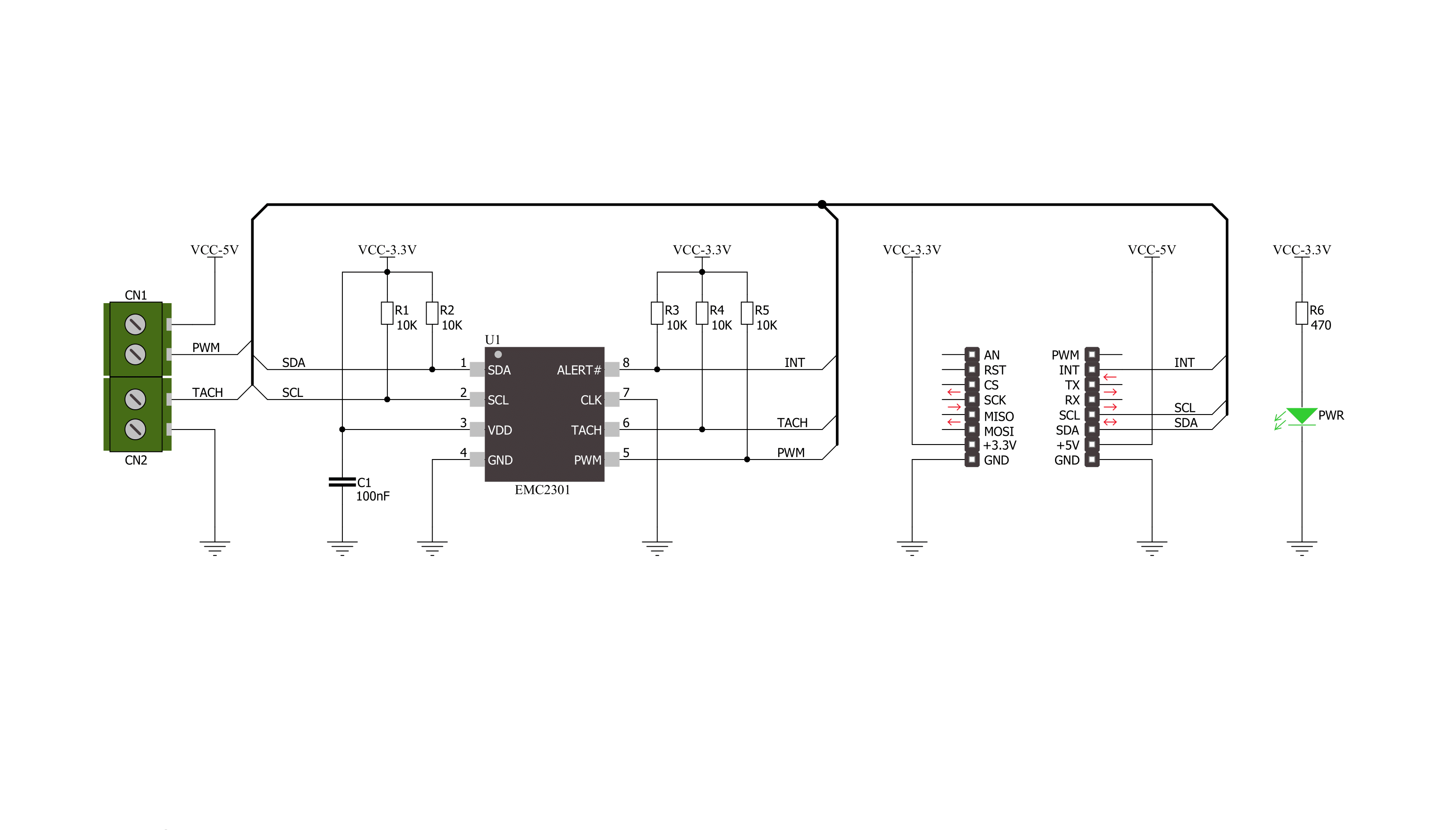
Fan Click is based on the EMS2301, a single/multiple RPM-based PWM fan controller from Microchip. The EMS2301 uses a programmable frequency driver and RPM-based algorithm with an internal clock to allow you to regulate the RPM of a given fan with 1% accuracy from 500 to 16K RPM. It also provides tachometer feedback for fan speed control available on TACH onboard terminal. The Fan Click can operate in either a closed-loop fashion or as a directly PWM-controlled device. In a closed loop, the Fan Speed Control (FSC) algorithm can detect aging, stalled, or locked fans and will trigger an interrupt.
In the FSC mode user determines a target tachometer count, and the PWM drive setting is automatically updated to achieve this target speed. This Click board™ communicates with MCU using the standard I2C 2-Wire interface to read data and configure settings, supporting a Fast Mode operation up to 400kHz. The EMS2301 monitors the fans' tachometer signals to detect fan failure, and when the tachometer count is larger than the fan tachometer limit, the fan is considered failing. If that happens, the alert is triggered over the interrupt INT pin. Meanwhile, the fan driver attempts to alleviate a Stalled/Stack
fan condition. Although a 3.3V voltage level only, this Click board™ uses a 5V rail to power a 4-wire fan over a 4-pin screw terminal. This board does not support an external power supply for the fan. This Click board™ can only be operated with a 3.3V logic voltage level. The board must perform appropriate logic voltage level conversion before using MCUs with different logic levels. This Click board™ comes equipped with a library containing functions and an example code that can be used as a reference for further development.

Features overview
Development board
PIC32MZ Clicker is a compact starter development board that brings the flexibility of add-on Click boards™ to your favorite microcontroller, making it a perfect starter kit for implementing your ideas. It comes with an onboard 32-bit PIC32MZ microcontroller with FPU from Microchip, a USB connector, LED indicators, buttons, a mikroProg connector, and a header for interfacing with external electronics. Thanks to its compact design with clear and easy-recognizable silkscreen markings, it provides a fluid and immersive working experience, allowing access anywhere and under
any circumstances. Each part of the PIC32MZ Clicker development kit contains the components necessary for the most efficient operation of the same board. In addition to the possibility of choosing the PIC32MZ Clicker programming method, using USB HID mikroBootloader, or through an external mikroProg connector for PIC, dsPIC, or PIC32 programmer, the Clicker board also includes a clean and regulated power supply module for the development kit. The USB Micro-B connection can provide up to 500mA of current, which is more than enough to operate all onboard
and additional modules. All communication methods that mikroBUS™ itself supports are on this board, including the well-established mikroBUS™ socket, reset button, and several buttons and LED indicators. PIC32MZ Clicker is an integral part of the Mikroe ecosystem, allowing you to create a new application in minutes. Natively supported by Mikroe software tools, it covers many aspects of prototyping thanks to a considerable number of different Click boards™ (over a thousand boards), the number of which is growing every day.

Microcontroller Overview
MCU Card / MCU

Architecture
PIC32
MCU Memory (KB)
1024
Silicon Vendor
Microchip
Pin count
64
RAM (Bytes)
524288
Used MCU Pins
mikroBUS™ mapper
Take a closer look
Click board™ Schematic
Step by step
Project assembly

Start by selecting your development board and Click board™. Begin with the PIC32MZ clicker as your development board.


Software Support
Library Description
This library contains API for Fan Click driver.
Key functions:
fan_generic_write- Generic write functionfan_generic_read- Generic read functionfan_lock_registers- Fan click lock registers
Open Source
Code example
The complete application code and a ready-to-use project are available through the NECTO Studio Package Manager for direct installation in the NECTO Studio. The application code can also be found on the MIKROE GitHub account.
/*!
 * \file main.c
 * \brief Fan Click Example
 *
 * # Description
 * This application is controller for powering and regulating of fan.
 *
 * The demo application is composed of two sections :
 *
 * ## Application Init
 * Initialization of Click driver and usb uart serial terminal for results
 * logging.
 *
 * ## Application Task
 * Performs a control of the fan and reads rotation per minute (RPM).
 * Results will be sent to the usb uart terminal.
 *
 * \author Nemanja Medakovic
 *
 */
// ------------------------------------------------------------------- INCLUDES

#include "board.h"
#include "log.h"
#include "fan.h"


#define FAN_DUTY_RATIO_0_PER    0       /**< PWM duty ratio 0 pecrents - zero scale. >*/
#define FAN_DUTY_RATIO_10_PER   10      /**< PWM duty ratio 10 percents - step. >*/
#define FAN_DUTY_RATIO_100_PER  100     /**< PWM duty ratio 100 percents - full scale. >*/

#define FAN_PWM_BASE_FREQ_ZERO_SCALE  0x00  /**< PWM base frequency zero scale. >*/
#define FAN_PWM_BASE_FREQ_HALF_SCALE  0x80  /**< PWM base frequency half scale. >*/
#define FAN_PWM_BASE_FREQ_FULL_SCALE  0xFF  /**< PWM base frequency full scale. >*/

// ------------------------------------------------------------------ VARIABLES

static fan_t fan;       /**< Fan Click object. >*/
static log_t logger;    /**< Logger object. >*/

// ------------------------------------------------------ APPLICATION FUNCTIONS

void application_init ( void )
{
    log_cfg_t log_cfg;
    fan_cfg_t fan_cfg;

    /**
     * Logger initialization.
     * Default baud rate: 115200
     * Default log level: LOG_LEVEL_DEBUG
     * @note If USB_UART_RX and USB_UART_TX
     * are defined as HAL_PIN_NC, you will
     * need to define them manually for log to work.
     * See @b LOG_MAP_USB_UART macro definition for detailed explanation.
     */
    LOG_MAP_USB_UART( log_cfg );
    log_init( &logger, &log_cfg );
    log_info( &logger, "---- Application Init ----" );

    //  Click initialization.

    fan_cfg_setup( &fan_cfg );
    FAN_MAP_MIKROBUS( fan_cfg, MIKROBUS_1 );
    if ( fan_init( &fan, &fan_cfg ) == I2C_MASTER_ERROR )
    {
        log_info( &logger, "---- Application Init Error ----" );
        log_info( &logger, "---- Please, run program again ----" );

        for ( ; ; );
    }
    log_info( &logger, "---- Application Init Done ----" );
    fan_default_cfg( &fan );
    fan_pwm_base( &fan, FAN_PWM_BASE_FREQ_HALF_SCALE );
    log_info( &logger, "---- Application Program Running... ----\n" );
}

void application_task ( void )
{
    for ( uint8_t duty = FAN_DUTY_RATIO_0_PER; duty <= FAN_DUTY_RATIO_100_PER;
          duty += FAN_DUTY_RATIO_10_PER )
    {
        fan_setting( &fan, duty );
        log_printf( &logger, " Duty Ratio : %u%%\r\n", (uint16_t)duty );
        Delay_ms ( 1000 );
        Delay_ms ( 1000 );

        uint16_t tacho = 0;

        fan_get_tach( &fan, &tacho );
        log_printf( &logger, " Rotation per minute : %urpm\r\n\n", tacho );
        Delay_ms ( 1000 );
        Delay_ms ( 1000 );
    }
}

int main ( void )
{
    /* Do not remove this line or clock might not be set correctly. */
    #ifdef PREINIT_SUPPORTED
    preinit();
    #endif

    application_init( );

    for ( ; ; )
    {
        application_task( );
    }

    return 0;
}

// ------------------------------------------------------------------------ END
Additional Support
Resources
Category:Brushless


