Develop a highly effective power management solution with MAX77654 and PIC32MZ1024EFH064
Elevate your batteries with our expertise

Published Aug 03, 2023
Click board™
BATT-MAN 2 Click
Dev. board
PIC32MZ clicker
Compiler
NECTO Studio
MCU
PIC32MZ1024EFH064
Ensure precise charging, safeguard against overcharging and overheating, and monitor battery health in real time
A
A
Hardware Overview
How does it work?
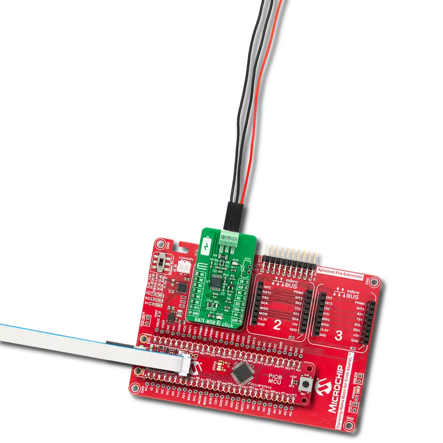
BATT-MAN 2 Click is based on the MAX77654, a highly-integrated battery charging and power management solution for low-power applications from Analog Devices. It features a single-inductor, multiple-output (SIMO) buck-boost regulator efficiently that provides three independently programmable power rails available on onboard terminals labeled VSB0, VSB1, and VSB2. Also, it has one 100mA LDO output, labeled as VLDO, with ripple rejection for audio and other noise-sensitive applications. This LDO output can also be configured as a load switch to manage power consumption by disconnecting external blocks when not required. The LDO output can be activated/deactivated by populating the JP2 onboard jumper. The MAX77654 also has an integrated highly-configurable linear charger that supports a wide range of Li+ battery capacities with a wide range of charge current and charger termination voltage options, featuring battery temperature monitoring for additional safety (JEITA). The charger feature is OFF when the CHG
supply is invalid (supply range from 4.1V up to 7.25V), disabled, or with a fresh battery. In addition to all the output terminals on this board, another one is marked with VSYS, the system power output terminal. In addition to providing power to the system resources and the device's control logic, VSYS is also designed for external use. BATT-MAN 2 Click communicates with MCU using the standard I2C 2-Wire interface for configuring and checking the device's status. Since the sensor for operation requires a 1.8V logic voltage level to work correctly, a small regulating LDO is used, the ADP160 from Analog Devices, providing a 1.8V out of mikroBUS™ rails. That's why the voltage-level translator is also featured. The I2C interface bus lines are routed to the dual bidirectional voltage-level translator, allowing this Click board™ to work properly with 3.3V and 5V MCUs. An onboard switch labeled as ENABLE primarily generates a wake-up signal for the PMIC that turns ON the regulators by setting the switch to an appropriate position marked as 1 or 0. In addition, this Click
board™ also has some additional features, such as a Reset routed to the RST pin on the mikroBUS™ socket used to hold the processor in a Reset state when the device is powered down. It also uses an interrupt pin, the INT pin of the mikroBUS™ socket, to signal an essential change in device status, while the three additional LED indicators, red, yellow, and blue LEDs labeled as LED2, LED3, and LED4, can be used for optional user-configurable visual indication. Besides, this device includes an analog multiplexer (AMX), routed to the AN pin on the mikroBUS™ socket, that switches several internal voltage and current signals to an external node for monitoring with an external ADC. This Click board™ can operate with either 3.3V or 5V logic voltage levels selected via the VCC SEL jumper. This way, both 3.3V and 5V capable MCUs can use the communication lines properly. Also, this Click board™ comes equipped with a library containing easy-to-use functions and an example code that can be used, as a reference, for further development.

Features overview
Development board
PIC32MZ Clicker is a compact starter development board that brings the flexibility of add-on Click boards™ to your favorite microcontroller, making it a perfect starter kit for implementing your ideas. It comes with an onboard 32-bit PIC32MZ microcontroller with FPU from Microchip, a USB connector, LED indicators, buttons, a mikroProg connector, and a header for interfacing with external electronics. Thanks to its compact design with clear and easy-recognizable silkscreen markings, it provides a fluid and immersive working experience, allowing access anywhere and under
any circumstances. Each part of the PIC32MZ Clicker development kit contains the components necessary for the most efficient operation of the same board. In addition to the possibility of choosing the PIC32MZ Clicker programming method, using USB HID mikroBootloader, or through an external mikroProg connector for PIC, dsPIC, or PIC32 programmer, the Clicker board also includes a clean and regulated power supply module for the development kit. The USB Micro-B connection can provide up to 500mA of current, which is more than enough to operate all onboard
and additional modules. All communication methods that mikroBUS™ itself supports are on this board, including the well-established mikroBUS™ socket, reset button, and several buttons and LED indicators. PIC32MZ Clicker is an integral part of the Mikroe ecosystem, allowing you to create a new application in minutes. Natively supported by Mikroe software tools, it covers many aspects of prototyping thanks to a considerable number of different Click boards™ (over a thousand boards), the number of which is growing every day.

Microcontroller Overview
MCU Card / MCU

Architecture
PIC32
MCU Memory (KB)
1024
Silicon Vendor
Microchip
Pin count
64
RAM (Bytes)
524288
Used MCU Pins
mikroBUS™ mapper
Take a closer look
Click board™ Schematic

Step by step
Project assembly

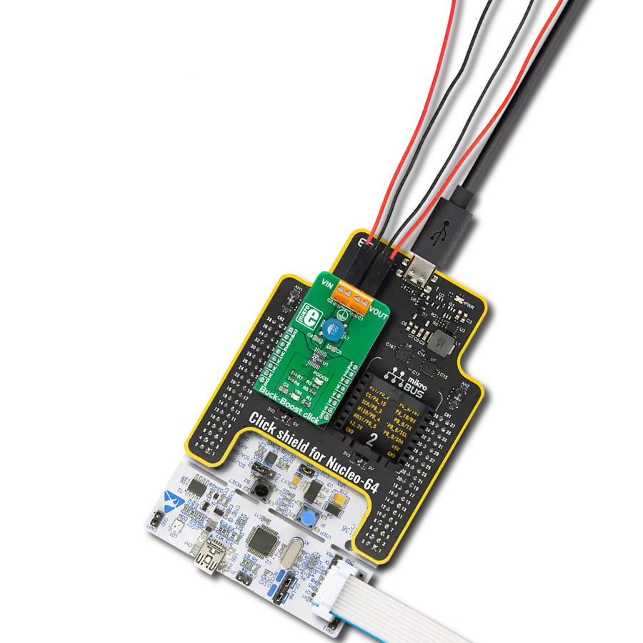
Start by selecting your development board and Click board™. Begin with the PIC32MZ clicker as your development board.


Track your results in real time
Application Output
1. Application Output - In Debug mode, the 'Application Output' window enables real-time data monitoring, offering direct insight into execution results. Ensure proper data display by configuring the environment correctly using the provided tutorial.

2. UART Terminal - Use the UART Terminal to monitor data transmission via a USB to UART converter, allowing direct communication between the Click board™ and your development system. Configure the baud rate and other serial settings according to your project's requirements to ensure proper functionality. For step-by-step setup instructions, refer to the provided tutorial.

3. Plot Output - The Plot feature offers a powerful way to visualize real-time sensor data, enabling trend analysis, debugging, and comparison of multiple data points. To set it up correctly, follow the provided tutorial, which includes a step-by-step example of using the Plot feature to display Click board™ readings. To use the Plot feature in your code, use the function: plot(*insert_graph_name*, variable_name);. This is a general format, and it is up to the user to replace 'insert_graph_name' with the actual graph name and 'variable_name' with the parameter to be displayed.

Software Support
Library Description
This library contains API for BATT-MAN 2 Click driver.
Key functions:
battman2_set_charger_enable- BATT-MAN 2 set charger enable functionbattman2_set_charger_cfg- BATT-MAN 2 set charger configuration functionbattman2_get_charger_cfg- BATT-MAN 2 get charger configuration function
Open Source
Code example
The complete application code and a ready-to-use project are available through the NECTO Studio Package Manager for direct installation in the NECTO Studio. The application code can also be found on the MIKROE GitHub account.
/*!
 * @file main.c
 * @brief BATTMAN2 Click example
 *
 * # Description
 * This library contains API for BATT-MAN 2 Click driver.
 * The library initializes and defines the I2C bus drivers
 * to write and read data from registers.
 * The library also includes a function for configuring appropriate charge current,
 * charge voltage, prequalification voltage,
 * Buck, Buck-Boost and Linear regulator configuration, etc.
 *
 * The demo application is composed of two sections :
 *
 * ## Application Init
 * The initialization of the I2C module, log UART, and additional pins.
 * After the driver inits and executes a default configuration,
 * the app disables charging, sets charger configuration,
 * enables charging, displays charger configuration,
 * or sets Buck-Boost configuration.
 *
 * ## Application Task
 * This is an example that shows the use of a BATT-MAN 2 Click board™.
 * The choice of example profile tasks depends on uncommented code.
 * Examples profile: CHARGER and BUCK-BOOST.
 * In the CHARGER profile, while on the BATT-MAN 2 Click board™ the
 * blue LED is the battery charging indicator,
 * while the red LED indicates the cessation of battery charging.
 * The yellow LED is an indicator of the BUCK-BOOST profile.
 * Results are being sent to the USART terminal where the user can track their changes.
 *
 * ## Additional Function
 * - static void display_charger_status ( void )
 * - static void display_sbb_status ( void )
 *
 * @author Nenad Filipovic
 *
 */

#include "board.h"
#include "log.h"
#include "battman2.h"

#define CHARGER
// #define BUCKBOOST

static battman2_t battman2;
static log_t logger;
static battman2_chg_cnfg_t chg_cfg;
static battman2_stat_chg_t chg_stat;
static battman2_sbb_cnfg_t sbb_cfg;
static uint8_t sbb_sel;

static void display_charger_status ( void )
{
    log_printf( &logger, " Charger Details :\r\n" );
    if ( chg_stat.chg_dtls == BATTMAN2_CHG_DTLS_OFF )
    {
        log_printf( &logger, "\tOff.\r\n" );
    }
    if ( chg_stat.chg_dtls == BATTMAN2_CHG_DTLS_PREQUALIFICATION_MODE )
    {
        log_printf( &logger, "\tPrequalification mode.\r\n" );
    }
    if ( chg_stat.chg_dtls == BATTMAN2_CHG_DTLS_FAST_CHARGE_CONSTANT_CURRENT )
    {
        log_printf( &logger, "\tFast-charge constant-current (CC) mode.\r\n" );
    }
    if ( chg_stat.chg_dtls == BATTMAN2_CHG_DTLS_JEITA_MODIFIED_FAST_CHRG_CC )
    {
        log_printf( &logger, "\tJEITA modified fast-charge constantcurrent mode.\r\n" );
    }
    if ( chg_stat.chg_dtls == BATTMAN2_CHG_DTLS_FAST_CHARGE_CONSTANT_VOLTAGE )
    {
        log_printf( &logger, "\tFast-charge constant-voltage (CV) mode.\r\n" );
    }
    if ( chg_stat.chg_dtls == BATTMAN2_CHG_DTLS_JEITA_MODIFIED_FAST_CHRG_CV )
    {
        log_printf( &logger, "\tJEITA modified fast-charge constant voltage (CV) mode.\r\n" );
    }
    if ( chg_stat.chg_dtls == BATTMAN2_CHG_DTLS_TOP_OFF_MODE )
    {
        log_printf( &logger, "\tTop-off mode.\r\n" );
    }
    if ( chg_stat.chg_dtls == BATTMAN2_CHG_DTLS_JEITA_MODIFIED_TOP_OFF_MODE )
    {
        log_printf( &logger, "\tJEITA modified top-off mode.\r\n" );
    }
    if ( chg_stat.chg_dtls == BATTMAN2_CHG_DTLS_DONE )
    {
        log_printf( &logger, "\tDone.\r\n" );
    }
    if ( chg_stat.chg_dtls == BATTMAN2_CHG_DTLS_JEITA_MODIFIED_DONE )
    {
        log_printf( &logger, "\tJEITA modified done.\r\n" );
    }
    if ( chg_stat.chg_dtls == BATTMAN2_CHG_DTLS_PREQUALIFICATION_TIMER_FAULT )
    {
        log_printf( &logger, "\tPrequalification timer fault.\r\n" );
    }
    if ( chg_stat.chg_dtls == BATTMAN2_CHG_DTLS_FAST_CHARGE_TIMER_FAULT )
    {
        log_printf( &logger, "\tFast-charge timer fault.\r\n" );
    }
    if ( chg_stat.chg_dtls == BATTMAN2_CHG_DTLS_BATTERY_TEMPERATURE_FAULT )
    {
        log_printf( &logger, "\tBattery temperature fault.\r\n" );
    }

    log_printf( &logger, " Quick Charger Status :\r\n" );
    if ( chg_stat.chg == BATTMAN2_CHG_NO_CHARGING )
    {
        log_printf( &logger, "\tCharging is not happening.\r\n" );
        battman2_set_gpio_output( &battman2, BATTMAN2_SEL_LED_RED, BATTMAN2_PIN_STATE_ON );
        battman2_set_gpio_output( &battman2, BATTMAN2_SEL_LED_YELLOW, BATTMAN2_PIN_STATE_OFF );
        battman2_set_gpio_output( &battman2, BATTMAN2_SEL_LED_BLUE, BATTMAN2_PIN_STATE_OFF );
    }
     if ( chg_stat.chg == BATTMAN2_CHG_CHARGING )
    {
        log_printf( &logger, "\tCharging is happening.\r\n" );
        battman2_set_gpio_output( &battman2, BATTMAN2_SEL_LED_RED, BATTMAN2_PIN_STATE_OFF );
        battman2_set_gpio_output( &battman2, BATTMAN2_SEL_LED_YELLOW, BATTMAN2_PIN_STATE_OFF );
        battman2_set_gpio_output( &battman2, BATTMAN2_SEL_LED_BLUE, BATTMAN2_PIN_STATE_ON );
    }
    log_printf( &logger, "-----------------------------------------------\r\n" );
}

static void display_sbb_status ( void )
{
    log_printf( &logger, "\tSBB Channel    : VSB-%d\r\n", ( uint16_t ) sbb_sel );
    log_printf( &logger, "\tOperation Mode :" );
    if ( sbb_cfg.op_mode == BATTMAN2_OP_MODE_BUCK_AND_BOOST )
    {
        log_printf( &logger, " Buck-boost mode.\r\n" );
    }
    if ( sbb_cfg.op_mode == BATTMAN2_OP_MODE_BUCK )
    {
        log_printf( &logger, " Buck mode.\r\n" );
    }

    log_printf( &logger, "\tCurrent Limit  :" );
    if ( sbb_cfg.current_limit == BATTMAN2_CURRENT_LIMIT_1000_mA )
    {
        log_printf( &logger, " 1.000 A\r\n" );
    }
    if ( sbb_cfg.current_limit == BATTMAN2_CURRENT_LIMIT_750_mA )
    {
        log_printf( &logger, " 0.750 A\r\n" );
    }
    if ( sbb_cfg.current_limit == BATTMAN2_CURRENT_LIMIT_500_mA )
    {
        log_printf( &logger, " 0.500 A\r\n" );
    }
    if ( sbb_cfg.current_limit == BATTMAN2_CURRENT_LIMIT_333_mA )
    {
        log_printf( &logger, " 0.333 A\r\n" );
    }

    log_printf( &logger, "\tOutput Voltage : %.3f V\r\n", sbb_cfg.output_vtg );
    log_printf( &logger, "-----------------------------------------------\r\n" );
}

void application_init ( void )
{
    log_cfg_t log_cfg;            /**< Logger config object. */
    battman2_cfg_t battman2_cfg;  /**< Click config object. */

    /**
     * Logger initialization.
     * Default baud rate: 115200
     * Default log level: LOG_LEVEL_DEBUG
     * @note If USB_UART_RX and USB_UART_TX
     * are defined as HAL_PIN_NC, you will
     * need to define them manually for log to work.
     * See @b LOG_MAP_USB_UART macro definition for detailed explanation.
     */
    LOG_MAP_USB_UART( log_cfg );
    log_init( &logger, &log_cfg );
    log_info( &logger, " Application Init " );

    // Click initialization.
    battman2_cfg_setup( &battman2_cfg );
    BATTMAN2_MAP_MIKROBUS( battman2_cfg, MIKROBUS_1 );
    err_t init_flag = battman2_init( &battman2, &battman2_cfg );
    if ( I2C_MASTER_ERROR == init_flag )
    {
        log_error( &logger, " Application Init Error. " );
        log_info( &logger, " Please, run program again... " );

        for ( ; ; );
    }

    battman2_default_cfg ( &battman2 );
    log_info( &logger, " Application Task " );
    Delay_ms ( 100 );

    battman2_set_charger_enable( &battman2, BATTMAN2_SET_CHARGER_DISABLE );
    Delay_ms ( 100 );

    #ifdef CHARGER
        log_printf( &logger, "-----------------------------------------------\r\n" );
        log_printf( &logger, "                Example: CHARGER               \r\n" );

        chg_cfg.thm_hot           = BATTMAN2_THM_HOT_411_mV;
        chg_cfg.thm_warm          = BATTMAN2_THM_WARM_511_mV;
        chg_cfg.thm_cool          = BATTMAN2_THM_COOL_747_mV;
        chg_cfg.thm_cold          = BATTMAN2_THM_COLD_867_mV;
        chg_cfg.vchgin_min        = 4.2;
        chg_cfg.ichgin_lim        = 95.0;
        chg_cfg.i_pq              = BATTMAN2_I_PQ_10_PERCENTAGE;
        chg_cfg.chg_pq            = 3.0;
        chg_cfg.i_term            = BATTMAN2_I_TERM_5_PERCENTAGE;
        chg_cfg.t_topoff          = BATTMAN2_T_TOPOFF_0_MIN;
        chg_cfg.tj_reg            = BATTMAN2_TJ_REG_60_C;
        chg_cfg.vsys_reg          = 4.100;
        chg_cfg.chg_cc            = 112.5;
        chg_cfg.t_fast_chg        = BATTMAN2_T_FAST_CHG_TIMER_7_HOURS;
        chg_cfg.chg_cc_jeita      = 15.0;
        chg_cfg.thm_en            = BATTMAN2_THM_EN_THERMISTOR_DISABLED;
        chg_cfg.chg_cv            = 3.775;
        chg_cfg.usbs              = BATTMAN2_USBS_CHGIN_IS_NOT_SUSPENDED;
        chg_cfg.chg_cv_jeita      = 3.6;
        chg_cfg.imon_dischg_scale = BATTMAN2_IMON_DISCHG_SCALE_300_mA;
        chg_cfg.mux_sel           = BATTMAN2_MUX_SEL_MULTIPLEXER_DISABLED;

        battman2_set_charger_cfg( &battman2, chg_cfg );
        Delay_ms ( 100 );

        battman2_set_charger_enable( &battman2, BATTMAN2_SET_CHARGER_ENABLE );
        Delay_ms ( 100 );
    #endif

    #ifdef BUCKBOOST
        log_printf( &logger, "-----------------------------------------------\r\n" );
        log_printf( &logger, "              Example: BUCK-BOOST              \r\n" );

        sbb_sel = BATTMAN2_SBB_CH_1;
        sbb_cfg.output_vtg = 5.5;
        sbb_cfg.op_mode = BATTMAN2_OP_MODE_BUCK_AND_BOOST;
        sbb_cfg.current_limit = BATTMAN2_CURRENT_LIMIT_500_mA;
        sbb_cfg.active_discharge_enable = BATTMAN2_ACTIVE_DISCHARGE_ENABLE;
        sbb_cfg.enable_control = BATTMAN2_ENABLE_CONTROL_ON_IRRESPECTIVE_FPS;
        sbb_cfg.ichgin_lim_def = BATTMAN2_ICHGIN_LIM_95_mA;
        sbb_cfg.drv_sbb = BATTMAN2_DRV_SBB_FAST_TRANSITION_TIME;
        battman2_set_sbb_config( &battman2, sbb_sel, sbb_cfg );
        log_printf( &logger, "-----------------------------------------------\r\n" );
        battman2_set_gpio_output( &battman2, BATTMAN2_SEL_LED_RED, BATTMAN2_PIN_STATE_OFF );
        battman2_set_gpio_output( &battman2, BATTMAN2_SEL_LED_YELLOW, BATTMAN2_PIN_STATE_ON );
        battman2_set_gpio_output( &battman2, BATTMAN2_SEL_LED_BLUE, BATTMAN2_PIN_STATE_OFF );
        Delay_ms ( 1000 );
    #endif
}

void application_task ( void )
{
    #ifdef CHARGER
        battman2_get_chg_status( &battman2, &chg_stat );
        Delay_ms ( 10 );

        display_charger_status( );
        Delay_ms ( 1000 );

        battman2_get_charger_cfg( &battman2, &chg_cfg );
        log_printf( &logger, " Fast-charge constant current value : %.1f mA\r\n", chg_cfg.chg_cc );
        log_printf( &logger, " Minimum CHGIN Regulation Voltage   : %.3f V\r\n", chg_cfg.vchgin_min );
        log_printf( &logger, " Battery Prequalific. Voltage Thld  : %.3f V\r\n", chg_cfg.chg_pq );
        log_printf( &logger, " System Voltage Regulation          : %.3f V\r\n", chg_cfg.vsys_reg );
        log_printf( &logger, " JEITA Ifast-chg-jeita              : %.2f mA\r\n", chg_cfg.chg_cc_jeita );
        log_printf( &logger, " Fast-charge battery Vreg           : %.3f V\r\n", chg_cfg.chg_cv );
        log_printf( &logger, " Vfast-chg-jeita                    : %.3f V\r\n", chg_cfg.chg_cv_jeita );
        log_printf( &logger, "-----------------------------------------------\r\n" );
        Delay_ms ( 1000 );
    #endif

    #ifdef BUCKBOOST
        battman2_get_sbb_config( &battman2, sbb_sel, &sbb_cfg );
        Delay_ms ( 10 );

        display_sbb_status( );
        Delay_ms ( 1000 );
    #endif
}

int main ( void )
{
    /* Do not remove this line or clock might not be set correctly. */
    #ifdef PREINIT_SUPPORTED
    preinit();
    #endif

    application_init( );

    for ( ; ; )
    {
        application_task( );
    }

    return 0;
}

// ------------------------------------------------------------------------ END
Additional Support
Resources
Category:Buck-Boost