Elevate your IoT devices with Thingstream's instant global connectivity using SIM868 and PIC32MZ1024EFH064
One gateway, endless connectivity

Published Aug 30, 2023
Click board™
Thingstream Click
Dev. board
PIC32MZ clicker
Compiler
NECTO Studio
MCU
PIC32MZ1024EFH064
Our IoT gateway solution, equipped with the Thingstream client SDK, revolutionizes device connectivity by enabling immediate access to the Thingstream global MQTT network and a suite of connectivity tools right out of the box
A
A
Hardware Overview
How does it work?
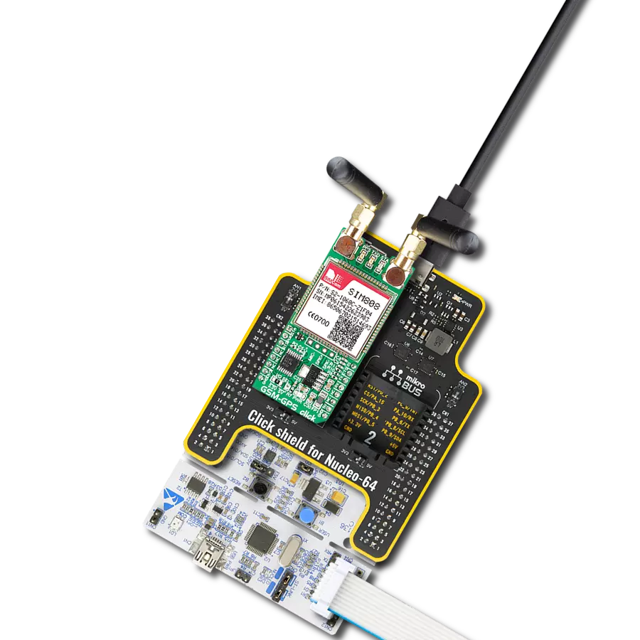
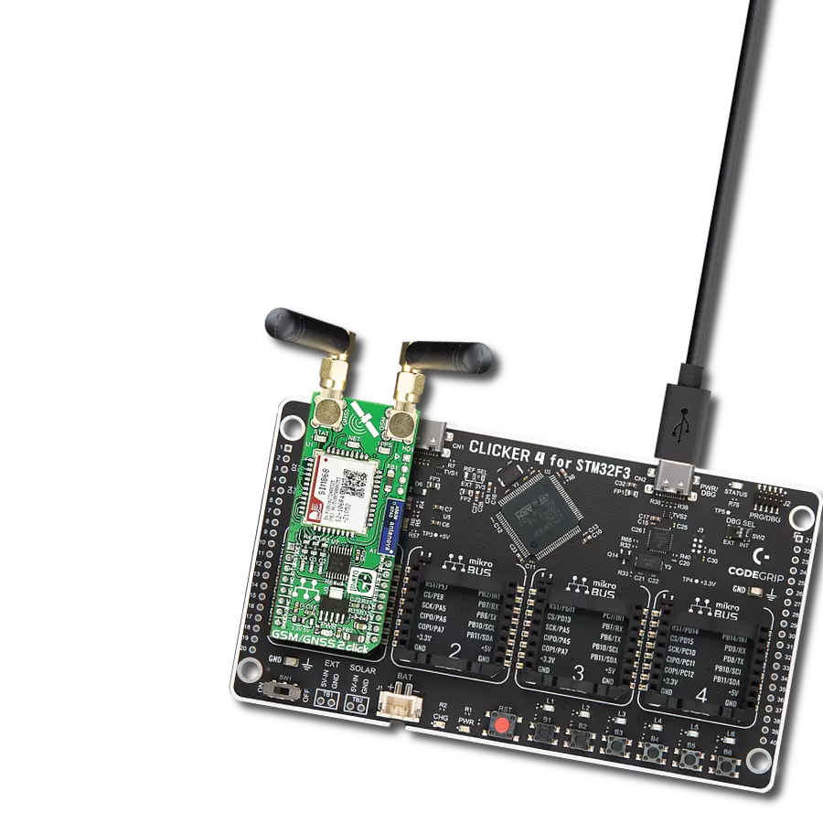
Thingstream Click is based on the SIM868, an 802.11b/g/n quad-band GPS/GLONASS/GSM location tracking and mobile communication module from SIMCom. This lets the device connect to the Thingstream global MQTT network over GSM. Thingstream Click enables rapid development of intelligent IoT applications and simplified connectivity with cloud platforms using just a small set of AT commands and a flow-chart style application builder (Data Flow Manager), removing the complexities of web, hardware, and communications-related development. This Click board™ is preconfigured with the protocols and communications settings to connect with the Thingstream global MQTT network and Data Flow Manager. This is implemented via the
Thingstream client SDK, which can be used to develop the firmware on the onboard STM32F407 MCU. Results can be achieved quickly without a deep understanding of software engineering and web programming. Thingstream Click is equipped with various LED indicators. Separate LEDs indicate the presence of a power supply, the network status, and pulse per second indication (1PPS). This Click board™ also contains a universal RGB LED for other feedback relating to the status of the Thingstream Click. This Click board™ requires a 5V power rail for proper operation. Besides the onboard USB connector, all of the mikroBUS™ pins on this Click board™ are routed to the appropriate pins of the onboard STM32F407 MCU. That way, it is ensured that users will have
plenty of space for future upgrades and development. This enables a broad range of custom applications, including support for I2C and SPI communication interfaces. All available interfaces can be made available to the mikroBUS header. By default, the board only supports UART communication using AT commands. Firmware updates can support other interfaces like SPI, I2C, PWM, and Analog. This Click board™ can be operated only with a 3.3V logic voltage level. The board must perform appropriate logic voltage level conversion before using MCUs with different logic levels. Also, it comes equipped with a library containing functions and an example code that can be used as a reference for further development.

Features overview
Development board
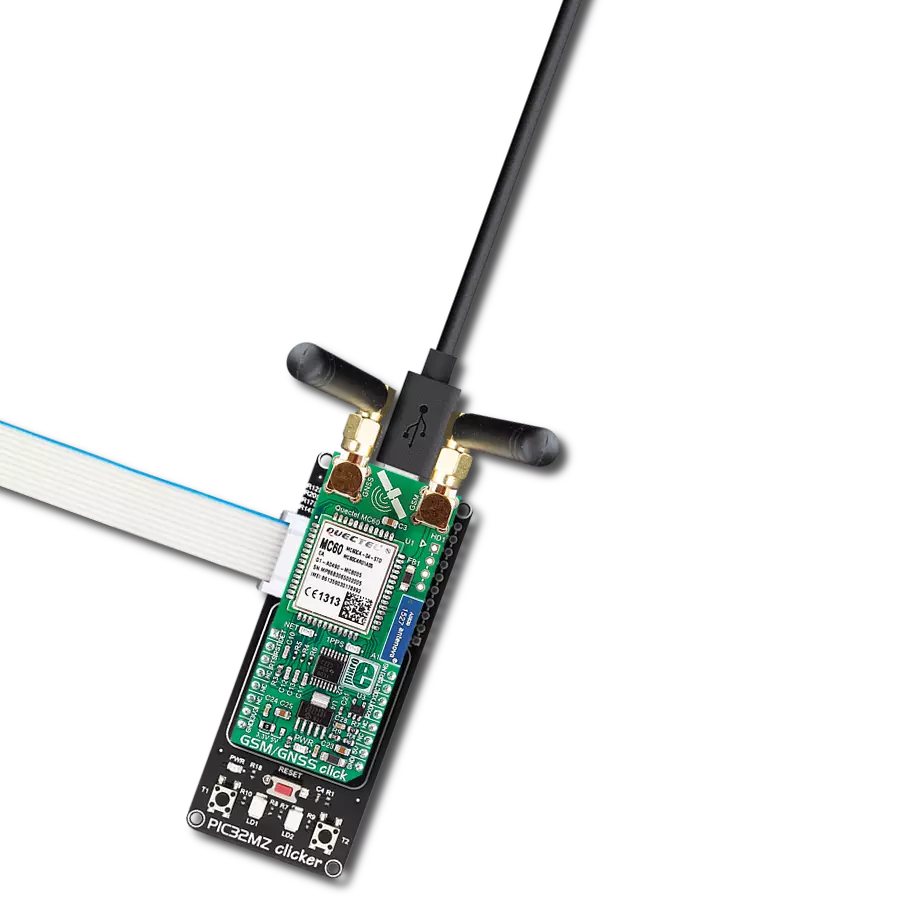
PIC32MZ Clicker is a compact starter development board that brings the flexibility of add-on Click boards™ to your favorite microcontroller, making it a perfect starter kit for implementing your ideas. It comes with an onboard 32-bit PIC32MZ microcontroller with FPU from Microchip, a USB connector, LED indicators, buttons, a mikroProg connector, and a header for interfacing with external electronics. Thanks to its compact design with clear and easy-recognizable silkscreen markings, it provides a fluid and immersive working experience, allowing access anywhere and under
any circumstances. Each part of the PIC32MZ Clicker development kit contains the components necessary for the most efficient operation of the same board. In addition to the possibility of choosing the PIC32MZ Clicker programming method, using USB HID mikroBootloader, or through an external mikroProg connector for PIC, dsPIC, or PIC32 programmer, the Clicker board also includes a clean and regulated power supply module for the development kit. The USB Micro-B connection can provide up to 500mA of current, which is more than enough to operate all onboard
and additional modules. All communication methods that mikroBUS™ itself supports are on this board, including the well-established mikroBUS™ socket, reset button, and several buttons and LED indicators. PIC32MZ Clicker is an integral part of the Mikroe ecosystem, allowing you to create a new application in minutes. Natively supported by Mikroe software tools, it covers many aspects of prototyping thanks to a considerable number of different Click boards™ (over a thousand boards), the number of which is growing every day.

Microcontroller Overview
MCU Card / MCU

Architecture
PIC32
MCU Memory (KB)
1024
Silicon Vendor
Microchip
Pin count
64
RAM (Bytes)
524288
You complete me!
Accessories
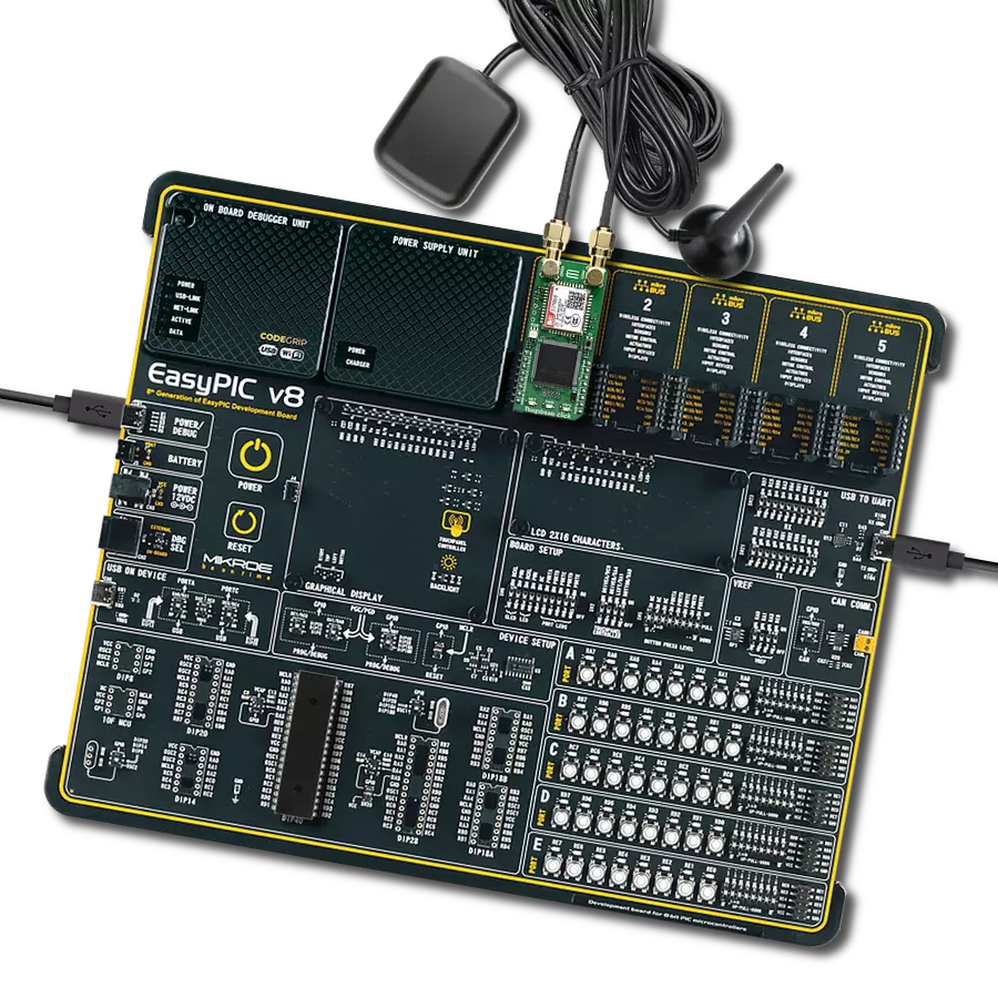
Active GPS antenna is designed to enhance the performance of your GPS and GNSS Click boards™. This external antenna boasts a robust construction, making it ideal for various weather conditions. With a frequency range of 1575.42MHz and a 50Ohm impedance, it ensures reliable signal reception. The antenna delivers a gain of greater than -4dBic within a wide angular range, securing over 75% coverage. The bandwidth of +/- 5MHz further guarantees precise data acquisition. Featuring a Right-Hand Circular Polarization (RHCP), this antenna offers stable signal reception. Its compact dimensions of 48.53915mm and a 2-meter cable make it easy to install. The magnetic antenna type with an SMA male connector ensures a secure and convenient connection. If you require a dependable external antenna for your locator device, our active GPS antenna is the perfect solution.

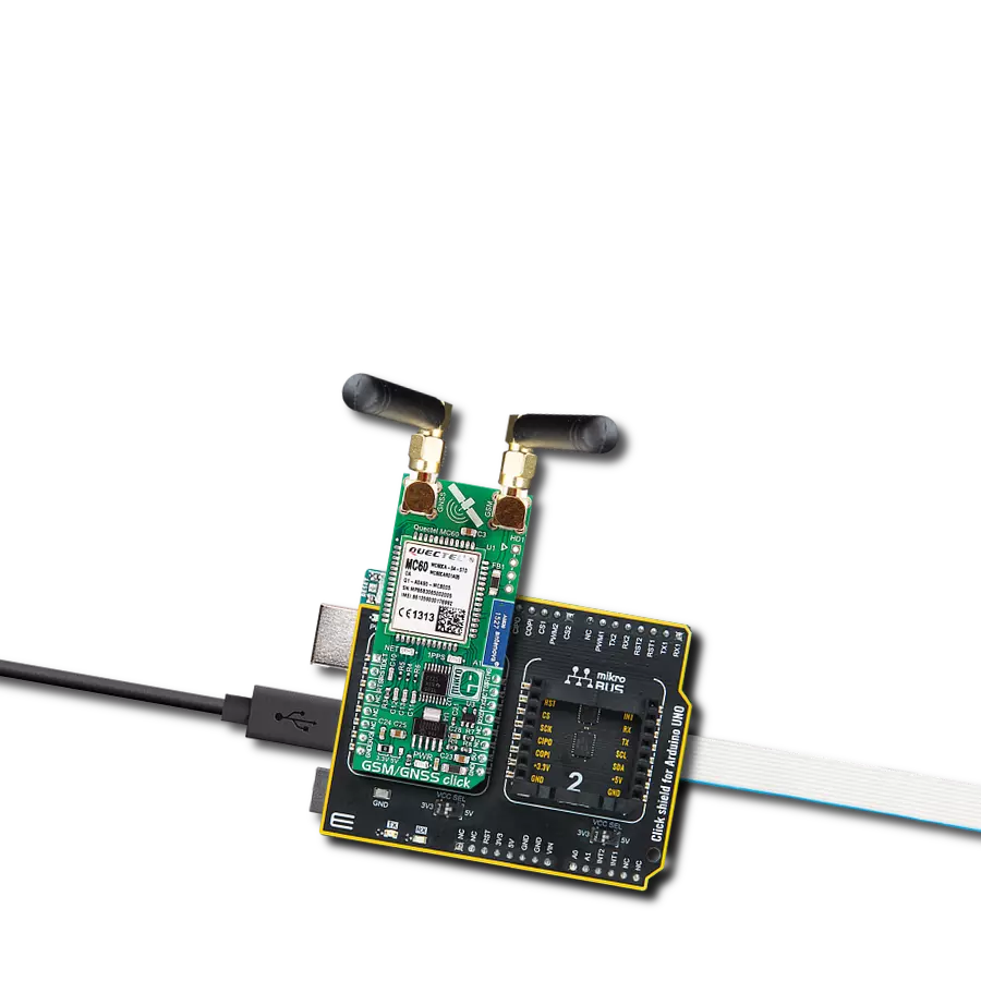
The GSM right-angle rubber antenna is a perfect match for our GSM Click boards™. With a wide bandwidth accommodating GSM/GPRS modules, this antenna has a 2m cable featuring an SMA male connector for easy positioning. Operating within a frequency range of 824-894/1710-1990MHz or 890-960/1710-1890MHz, it maintains a 50Ohm impedance, delivering a gain of 3dB. Its 90/280MHz bandwidth ensures reliable connectivity, while its vertical polarization optimizes signal reception. With a maximum input power of 60W, it offers robust performance. Measuring just 90mm in length, this magnetic antenna is compact yet powerful. Its SMA male connector ensures a secure and stable connection, making it an ideal choice for seamless integration with any GSM Click board™.

Used MCU Pins
mikroBUS™ mapper
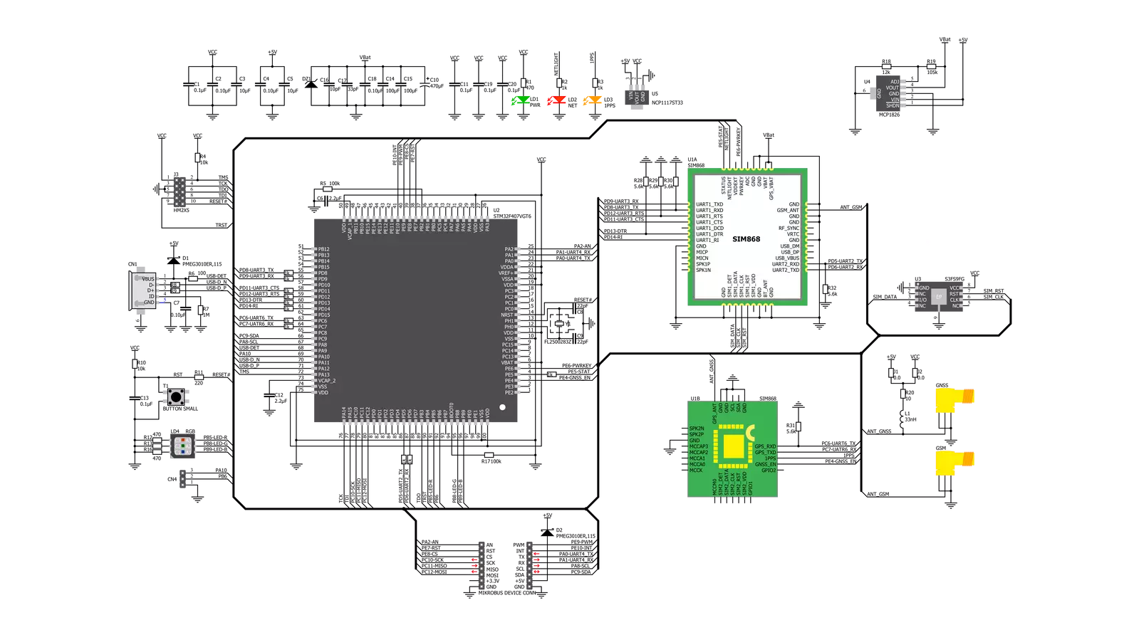
Take a closer look
Click board™ Schematic
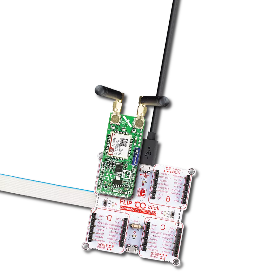
Step by step
Project assembly

Start by selecting your development board and Click board™. Begin with the PIC32MZ clicker as your development board.


Software Support
Library Description
This library contains API for Thingstream Click driver.
Key functions:
thingstream_reset_pin_state- Set RST pin statethingstream_send_command- Send commandthingstream_generic_parser- Generic parser function.
Open Source
Code example
The complete application code and a ready-to-use project are available through the NECTO Studio Package Manager for direct installation in the NECTO Studio. The application code can also be found on the MIKROE GitHub account.
/*!
 * \file
 * \brief Thingstream Click example
 *
 * # Description
 * This example reads and processes data from Thingstream Clicks.
 *
 * The demo application is composed of two sections :
 *
 * ## Application Init
 * Initializes driver and power module.
 *
 * ## Application Task
 * Reads the received data and parses it.
 *
 * ## Additional Function
 * - thingstream_process ( ) - The general process of collecting data the module sends.
 *
 * @note
 * The Click board needs to be registered with a redemption code to a Thingstream Domain.
 * For more information please refer to the Thingstream Click user manual available on the product page.
 *
 * \author MikroE Team
 *
 */
// ------------------------------------------------------------------- INCLUDES

#include "board.h"
#include "log.h"
#include "thingstream.h"
#include "string.h"

#define PROCESS_COUNTER 600
#define PROCESS_RX_BUFFER_SIZE 600
#define PROCESS_PARSER_BUFFER_SIZE 600

#define THINGSTREAM_INFO      "AT+IOTINFO"
#define THINGSTREAM_CREATE    "AT+IOTCREATE"
#define THINGSTREAM_CONNECT   "AT+IOTCONNECT=true"
#define THINGSTREAM_GPS_PWR   "AT+IOTCGNSPWR=1"
#define THINGSTREAM_SUBSCRIBE "AT+IOTSUBSCRIBE=\"home/temperature\",1"
#define THINGSTREAM_PUBLISH   "AT+IOTPUBLISH=\"home/temperature\",0,\"23 degrees\""
#define THINGSTREAM_GPS_INFO  "AT+IOTCGNSINF"

// ------------------------------------------------------------------ VARIABLES

static thingstream_t thingstream;
static log_t logger;

static char current_parser_buf[ PROCESS_PARSER_BUFFER_SIZE ];
static uint8_t send_data_cnt = 0;

// ------------------------------------------------------- ADDITIONAL FUNCTIONS

static void thingstream_process ( void )
{
    int32_t rsp_size = 0;
    uint16_t rsp_cnt = 0;

    char uart_rx_buffer[ PROCESS_RX_BUFFER_SIZE ] = { 0 };
    uint16_t check_buf_cnt = 0;
    uint16_t process_cnt = PROCESS_COUNTER;
    // Clear parser buffer
    memset( current_parser_buf, 0, PROCESS_PARSER_BUFFER_SIZE );

    while ( process_cnt != 0 )
    {
        rsp_size = thingstream_generic_read( &thingstream, uart_rx_buffer, PROCESS_RX_BUFFER_SIZE );

        if ( rsp_size > 0 )
        {
            // Validation of the received data
            for ( check_buf_cnt = 0; check_buf_cnt < rsp_size; check_buf_cnt++ )
            {
                if ( uart_rx_buffer[ check_buf_cnt ] == 0 )
                {
                    uart_rx_buffer[ check_buf_cnt ] = 13;
                }
            }
            // Storages data in parser buffer
            rsp_cnt += rsp_size;
            if ( rsp_cnt < PROCESS_PARSER_BUFFER_SIZE )
            {
                strncat( current_parser_buf, uart_rx_buffer, rsp_size );
            }
            if ( strchr( uart_rx_buffer, '+' ) )
            {
                process_cnt = 20;
            }
            // Clear RX buffer
            memset( uart_rx_buffer, 0, PROCESS_RX_BUFFER_SIZE );
        }
        else
        {
            process_cnt--;

            // Process delay
            Delay_ms ( 100 );
        }
    }
}

static void parser_application ( char *rsp )
{
    char element_buf[ 200 ] = { 0 };

    log_printf( &logger, "\r\n-----------------------\r\n" );
    thingstream_generic_parser( rsp, THINGSTREAM_NEMA_CGNSINF, THINGSTREAM_CGNSINF_LATITUDE, element_buf );
    if ( strlen( element_buf ) > 0 )
    {
        log_printf( &logger, "Latitude: %s degrees \r\n", element_buf );
        thingstream_generic_parser( rsp, THINGSTREAM_NEMA_CGNSINF, THINGSTREAM_CGNSINF_LONGITUDE, element_buf );
        log_printf( &logger, "Longitude: %s degrees \r\n", element_buf );
        memset( element_buf, 0, sizeof( element_buf ) );
        thingstream_generic_parser( rsp, THINGSTREAM_NEMA_CGNSINF, THINGSTREAM_CGNSINF_ALTITUDE, element_buf );
        log_printf( &logger, "Altitude: %s m", element_buf );
    }
    else
    {
        log_printf( &logger, "Waiting for the position fix..." );
    }
}

// ------------------------------------------------------ APPLICATION FUNCTIONS

void application_init ( void )
{
    log_cfg_t log_cfg;
    thingstream_cfg_t cfg;

    /**
     * Logger initialization.
     * Default baud rate: 115200
     * Default log level: LOG_LEVEL_DEBUG
     * @note If USB_UART_RX and USB_UART_TX
     * are defined as HAL_PIN_NC, you will
     * need to define them manually for log to work.
     * See @b LOG_MAP_USB_UART macro definition for detailed explanation.
     */
    LOG_MAP_USB_UART( log_cfg );
    log_init( &logger, &log_cfg );
    log_info( &logger, "---- Application Init ----" );

    // Click initialization.
    thingstream_cfg_setup( &cfg );
    THINGSTREAM_MAP_MIKROBUS( cfg, MIKROBUS_1 );
    thingstream_init( &thingstream, &cfg );

    thingstream_module_power( &thingstream, true );
    Delay_ms ( 1000 );
    Delay_ms ( 1000 );
    Delay_ms ( 1000 );

    log_printf( &logger, " --->>> INFO.. \r\n" );
    thingstream_send_command( &thingstream, THINGSTREAM_INFO );
    thingstream_process( );
    log_printf( &logger, "%s", current_parser_buf );

    log_printf( &logger, " --->>> CREATE.. \r\n" );
    thingstream_send_command( &thingstream, THINGSTREAM_CREATE );
    thingstream_process( );
    log_printf( &logger, "%s", current_parser_buf );

    log_printf( &logger, " --->>> CONNECT.. \r\n" );
    thingstream_send_command( &thingstream, THINGSTREAM_CONNECT );
    thingstream_process( );
    log_printf( &logger, "%s", current_parser_buf );

    log_printf( &logger, " --->>> GPS POWER.. \r\n" );
    thingstream_send_command( &thingstream, THINGSTREAM_GPS_PWR );
    thingstream_process( );
    log_printf( &logger, "%s", current_parser_buf );

    log_printf( &logger, " --->>> SUBSCRIBE.. \r\n" );
    thingstream_send_command( &thingstream, THINGSTREAM_SUBSCRIBE );
    thingstream_process( );
    log_printf( &logger, "%s", current_parser_buf );

    log_printf( &logger, " --->>> PUBLISH.. \r\n" );
    thingstream_send_command( &thingstream, THINGSTREAM_PUBLISH );
    thingstream_process( );
    log_printf( &logger, "%s", current_parser_buf );

    log_printf( &logger, " --->>> APP INIT <<<--- \r\n" );
}

void application_task ( void )
{
    thingstream_send_command( &thingstream, THINGSTREAM_GPS_INFO );
    thingstream_process( );
    parser_application( current_parser_buf );
}

int main ( void )
{
    /* Do not remove this line or clock might not be set correctly. */
    #ifdef PREINIT_SUPPORTED
    preinit();
    #endif

    application_init( );

    for ( ; ; )
    {
        application_task( );
    }

    return 0;
}

// ------------------------------------------------------------------------ END
Additional Support
Resources
Category:GSM+GPS