Rely on TLE7259-3 and PIC32MZ1024EFH064 to ensure reliable communication on the LIN bus
LIN transceivers: The silent heroes of modern vehicle and industrial systems

Published Sep 12, 2023
Click board™
LIN Click
Dev. board
PIC32MZ clicker
Compiler
NECTO Studio
MCU
PIC32MZ1024EFH064
Trust in our LIN transceiver for robust real-time monitoring and control in demanding industrial environments, ensuring precision and uptime.
A
A
Hardware Overview
How does it work?
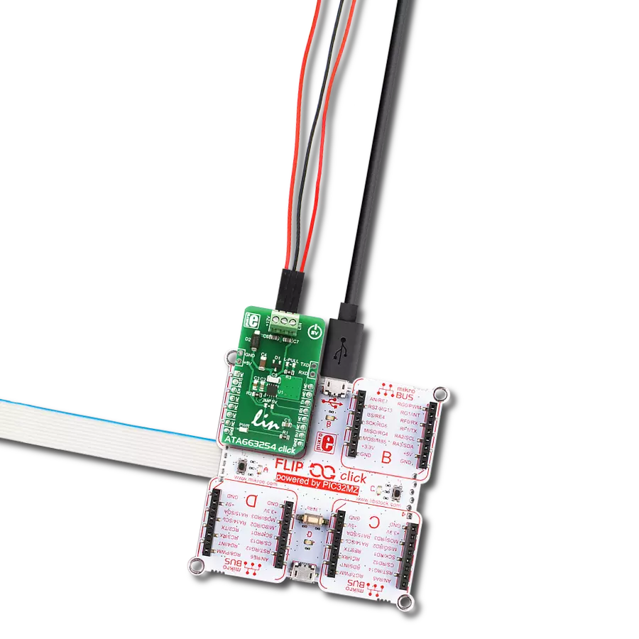
LIN Click is based on the TLE7259-3, a LIN transceiver with an integrated wake-up feature from Infineon Technologies. The TLE7259-3 operates as a bus driver between the protocol controller and the physical LIN bus designed for in-vehicle networks using data transmission rates from 2.4kbps to 20kbps. It is compliant with all LIN standards and has built-in protection features against over-voltage and overtemperature conditions and a wide operating supply range, making the TLE7259-3 ideal for various automotive applications. LIN Click communicates with MCU using the UART interface with commonly used UART RX and TX pins at 9600 bps by default configuration to transmit and exchange data with the host MCU. The transmit data stream on the TX input is converted to a LIN bus signal with an optimized slew rate, while the RX output reads back the information from the LIN bus to the MCU. The receiver also has an integrated filter network
to suppress noise on the LIN bus and increase the transceiver's EMI (Electromagnetic immunity) level. This Click board™ provides the ability to work in both Host or Peripheral mode, where selection can be performed by onboard SMD jumper labeled as MODE to an appropriate position. The TLE7259-3 also operates in three major operational modes: Stand-by, Normal, and Sleep mode, selected by the logic state of the enable pin labeled as EN and routed to the CS pin of the mikroBUS™ socket. In Normal Operation mode, the LIN bus receiver and the LIN bus transmitter are active, whereby communication occurs as usual, while in the Stand-by mode, no communication on the LIN bus is possible. Sleep mode significantly reduces the current consumption of the TLE7259-3. The LIN bus also has a wake-up event often called remote Wake-Up, a falling edge on the LIN bus followed by a specific duration, resulting in a wake-up event
that changes the operation mode from Sleep mode to Stand-by mode. Besides the remote wake-up, a wake-up of the TLE7259-3 via the WK pin routed to the PWM pin of the mikroBUS™ socket is possible, called local wake-up. This Click board™ supports an external power supply connected to the input terminal labeled as VS and should be within the range of 5.5V to 27V, suitable for both 12V and 24V board net, while the LIN bus line can be connected to the terminal labeled as BUS. This Click board™ can operate with either 3.3V or 5V logic voltage levels selected via the VCC SEL jumper. This way, both 3.3V and 5V capable MCUs can use the communication lines properly. Also, this Click board™ comes equipped with a library containing easy-to-use functions and an example code that can be used as a reference for further development.

Features overview
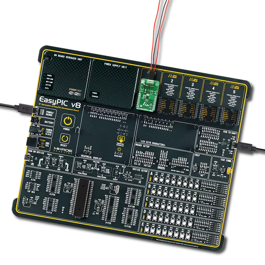
Development board
PIC32MZ Clicker is a compact starter development board that brings the flexibility of add-on Click boards™ to your favorite microcontroller, making it a perfect starter kit for implementing your ideas. It comes with an onboard 32-bit PIC32MZ microcontroller with FPU from Microchip, a USB connector, LED indicators, buttons, a mikroProg connector, and a header for interfacing with external electronics. Thanks to its compact design with clear and easy-recognizable silkscreen markings, it provides a fluid and immersive working experience, allowing access anywhere and under
any circumstances. Each part of the PIC32MZ Clicker development kit contains the components necessary for the most efficient operation of the same board. In addition to the possibility of choosing the PIC32MZ Clicker programming method, using USB HID mikroBootloader, or through an external mikroProg connector for PIC, dsPIC, or PIC32 programmer, the Clicker board also includes a clean and regulated power supply module for the development kit. The USB Micro-B connection can provide up to 500mA of current, which is more than enough to operate all onboard
and additional modules. All communication methods that mikroBUS™ itself supports are on this board, including the well-established mikroBUS™ socket, reset button, and several buttons and LED indicators. PIC32MZ Clicker is an integral part of the Mikroe ecosystem, allowing you to create a new application in minutes. Natively supported by Mikroe software tools, it covers many aspects of prototyping thanks to a considerable number of different Click boards™ (over a thousand boards), the number of which is growing every day.

Microcontroller Overview
MCU Card / MCU

Architecture
PIC32
MCU Memory (KB)
1024
Silicon Vendor
Microchip
Pin count
64
RAM (Bytes)
524288
Used MCU Pins
mikroBUS™ mapper
Take a closer look
Click board™ Schematic

Step by step
Project assembly

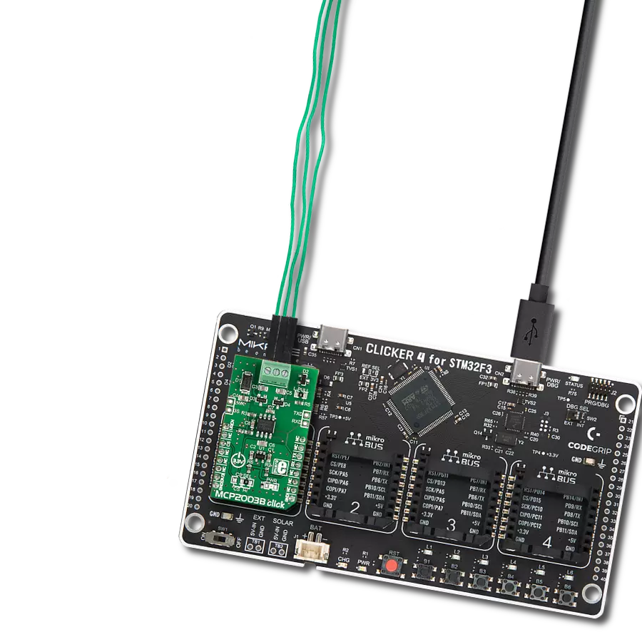
Start by selecting your development board and Click board™. Begin with the PIC32MZ clicker as your development board.


Software Support
Library Description
This library contains API for LIN Click driver.
Key functions:
lin_generic_write- Generic write functionlin_generic_read- Generic read functionlin_set_enable- Set enable pin state.
Open Source
Code example
The complete application code and a ready-to-use project are available through the NECTO Studio Package Manager for direct installation in the NECTO Studio. The application code can also be found on the MIKROE GitHub account.
/*!
 * \file
 * \brief Lin Click example
 *
 * # Description
 * This example reads and processes data from LIN Clicks.
 *
 * The demo application is composed of two sections :
 *
 * ## Application Init
 * Initializes the driver and makes an initial log.
 *
 * ## Application Task
 * Depending on the selected mode, it reads all the received data or sends the desired message
 * every 2 seconds.
 *
 * ## Additional Function
 * - lin_process ( ) - The general process of collecting the received data.
 *
 * @note
 * Make sure to set the onboard Master/Slave jumpers properly and to connect and power two Click
 * boards according to LIN Specification 2.2A.
 *
 * \author MikroE Team
 *
 */
// ------------------------------------------------------------------- INCLUDES

#include "board.h"
#include "log.h"
#include "lin.h"
#include "string.h"

#define PROCESS_RX_BUFFER_SIZE 500

#define TEXT_TO_SEND "MikroE - LIN Click board\r\n"

#define DEMO_APP_RECEIVER
// #define DEMO_APP_TRANSMITTER

// ------------------------------------------------------------------ VARIABLES

static lin_t lin;
static log_t logger;

// ------------------------------------------------------- ADDITIONAL FUNCTIONS

static void lin_process ( void )
{
    int32_t rsp_size;

    char uart_rx_buffer[ PROCESS_RX_BUFFER_SIZE ] = { 0 };

    rsp_size = lin_generic_read( &lin, uart_rx_buffer, PROCESS_RX_BUFFER_SIZE );

    if ( rsp_size > 0 )
    {
        for ( uint8_t cnt = 0; cnt < rsp_size; cnt++ )
        {
            log_printf( &logger, "%c", uart_rx_buffer[ cnt ] );
            if ( uart_rx_buffer[ cnt ] == '\n' )
            {
                log_printf( &logger, "---------------------------\r\n" );
            }
        }
    }
}

// ------------------------------------------------------ APPLICATION FUNCTIONS

void application_init ( void )
{
    log_cfg_t log_cfg;
    lin_cfg_t cfg;

    /**
     * Logger initialization.
     * Default baud rate: 115200
     * Default log level: LOG_LEVEL_DEBUG
     * @note If USB_UART_RX and USB_UART_TX
     * are defined as HAL_PIN_NC, you will
     * need to define them manually for log to work.
     * See @b LOG_MAP_USB_UART macro definition for detailed explanation.
     */
    LOG_MAP_USB_UART( log_cfg );
    log_init( &logger, &log_cfg );
    log_info( &logger, "---- Application Init ----" );

    //  Click initialization.

    lin_cfg_setup( &cfg );
    LIN_MAP_MIKROBUS( cfg, MIKROBUS_1 );
    lin_init( &lin, &cfg );
    Delay_ms ( 100 );

    lin_set_enable ( &lin, 1 );
    lin_set_wake_up ( &lin, 0 );
    Delay_ms ( 100 );
#ifdef DEMO_APP_RECEIVER
    log_info( &logger, "---- Receiver mode ----" );
#endif
#ifdef DEMO_APP_TRANSMITTER
    log_info( &logger, "---- Transmitter mode ----" );
#endif
}

void application_task ( void )
{
#ifdef DEMO_APP_RECEIVER
    lin_process( );
#endif

#ifdef DEMO_APP_TRANSMITTER
    lin_generic_write( &lin, TEXT_TO_SEND, strlen( TEXT_TO_SEND ) );
    log_info( &logger, "---- Data sent ----" );
    Delay_ms ( 1000 );
    Delay_ms ( 1000 );
#endif
}

int main ( void )
{
    /* Do not remove this line or clock might not be set correctly. */
    #ifdef PREINIT_SUPPORTED
    preinit();
    #endif

    application_init( );

    for ( ; ; )
    {
        application_task( );
    }

    return 0;
}

// ------------------------------------------------------------------------ END