Create innovative entertainment experiences with VZ43FC1B5640007L and PIC32MZ1024EFH064
Vibrate to your rhythm

Published Sep 10, 2023
Click board™
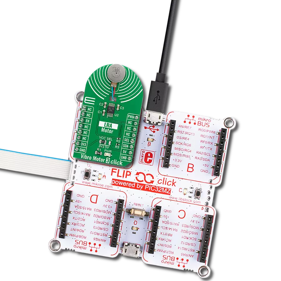
Vibro Motor 2 Click
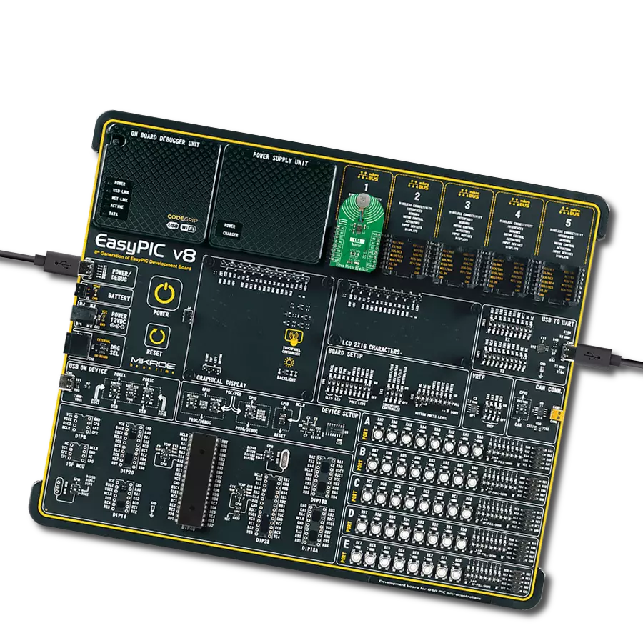
Dev. board
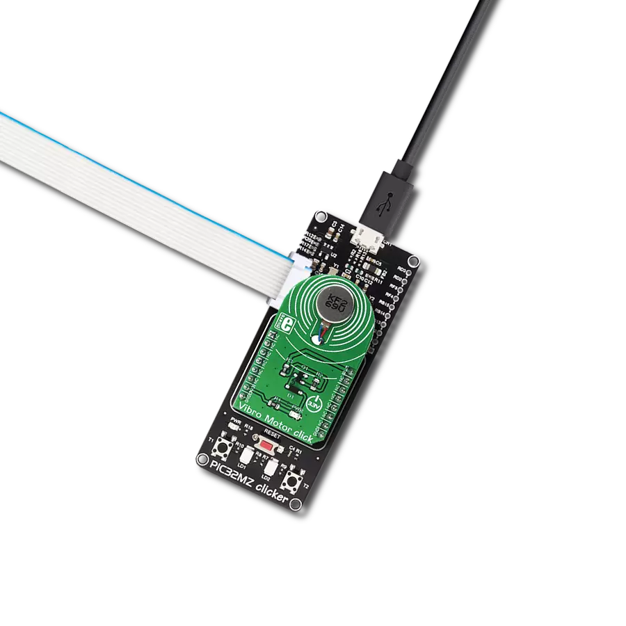
PIC32MZ clicker
Compiler
NECTO Studio
MCU
PIC32MZ1024EFH064
Elevate user interactions by incorporating controlled vibrations into your devices, providing tactile feedback that enhances user engagement
A
A
Hardware Overview
How does it work?
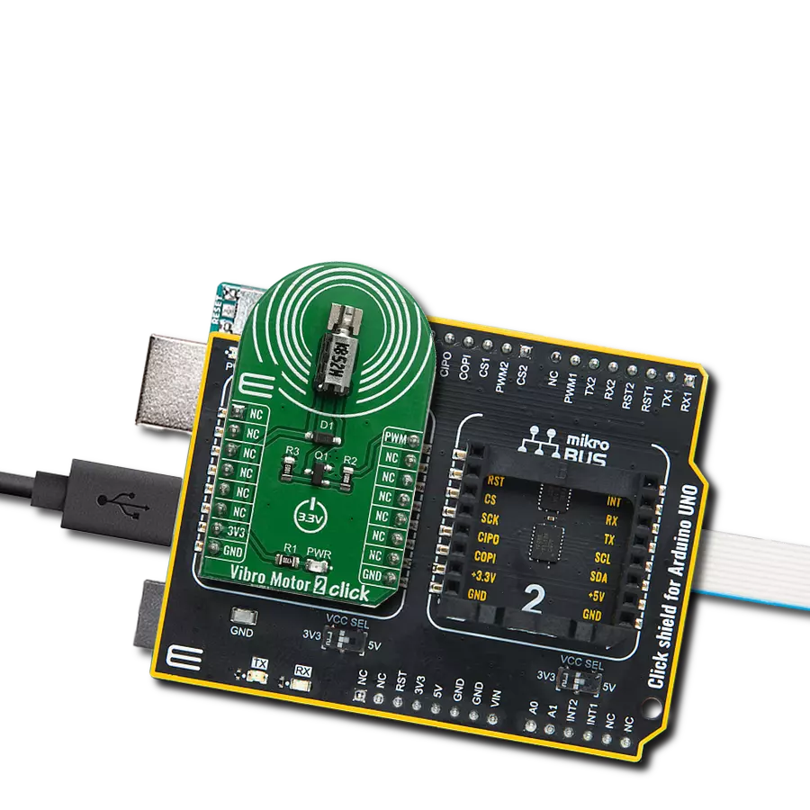
Vibro Motor 2 Click is based on the VZ43FC1B5640007L, a compact Eccentric Rotating Mass (ERM) motor that generates vibration/haptic feedback from Vybronics. This motor contains a small eccentric weight on its rotor, producing a vibration effect while rotating it. The VZ43FC1B5640007L draws a typical 100mA while creating a sizable vibration force of 0.91G and makes an excellent choice for applications requiring crisp haptic feedback and low power consumption. This Click board™ also uses the
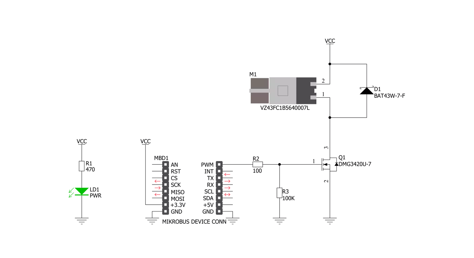
DMG3420U N-channel MOSFET to drive the ERM motor since the MCU cannot provide enough power for the motor driving. The PWM signal drives the gate of the MOSFET, routed to the PWM pin of the mikroBUS™ socket. The PWM signal toggles the MOSFET gate with pulses of a certain width. As a result, the current through the motor is varied depending on the pulse width of the PWM signal, which directly affects the speed of the motor, effectively controlling the vibration force that way. The circuit also contains a protection
diode, which protects the transistor from the reverse voltage since the motor represents an inductive load. Turning off its current can produce a kickback voltage that can damage the transistor. This Click board™ can be operated only with a 3.3V logic voltage level. The board must perform appropriate logic voltage level conversion before using MCUs with different logic levels. Also, it comes equipped with a library containing functions and an example code that can be used as a reference for further development.


Features overview
Development board
PIC32MZ Clicker is a compact starter development board that brings the flexibility of add-on Click boards™ to your favorite microcontroller, making it a perfect starter kit for implementing your ideas. It comes with an onboard 32-bit PIC32MZ microcontroller with FPU from Microchip, a USB connector, LED indicators, buttons, a mikroProg connector, and a header for interfacing with external electronics. Thanks to its compact design with clear and easy-recognizable silkscreen markings, it provides a fluid and immersive working experience, allowing access anywhere and under
any circumstances. Each part of the PIC32MZ Clicker development kit contains the components necessary for the most efficient operation of the same board. In addition to the possibility of choosing the PIC32MZ Clicker programming method, using USB HID mikroBootloader, or through an external mikroProg connector for PIC, dsPIC, or PIC32 programmer, the Clicker board also includes a clean and regulated power supply module for the development kit. The USB Micro-B connection can provide up to 500mA of current, which is more than enough to operate all onboard
and additional modules. All communication methods that mikroBUS™ itself supports are on this board, including the well-established mikroBUS™ socket, reset button, and several buttons and LED indicators. PIC32MZ Clicker is an integral part of the Mikroe ecosystem, allowing you to create a new application in minutes. Natively supported by Mikroe software tools, it covers many aspects of prototyping thanks to a considerable number of different Click boards™ (over a thousand boards), the number of which is growing every day.

Microcontroller Overview
MCU Card / MCU

Architecture
PIC32
MCU Memory (KB)
1024
Silicon Vendor
Microchip
Pin count
64
RAM (Bytes)
524288
Used MCU Pins
mikroBUS™ mapper
Take a closer look
Click board™ Schematic
Step by step
Project assembly

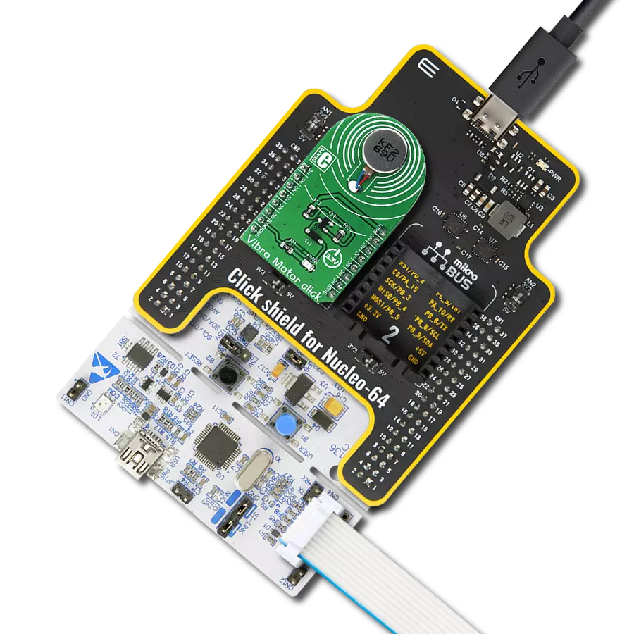
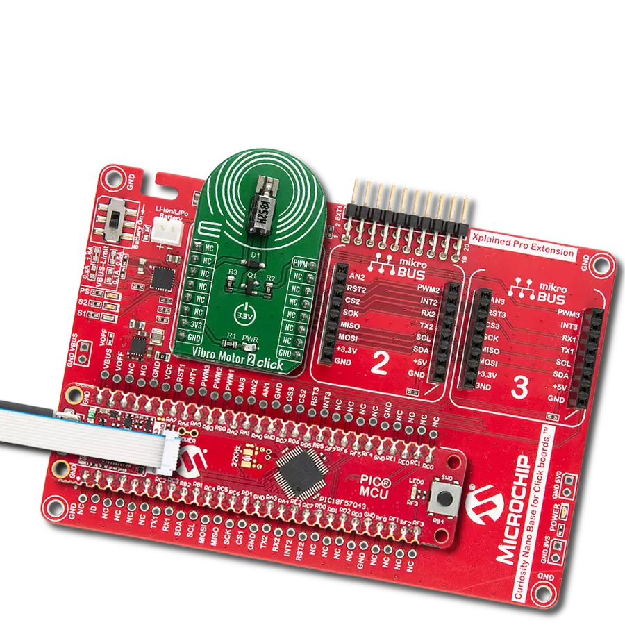
Start by selecting your development board and Click board™. Begin with the PIC32MZ clicker as your development board.


Track your results in real time
Application Output
1. Application Output - In Debug mode, the 'Application Output' window enables real-time data monitoring, offering direct insight into execution results. Ensure proper data display by configuring the environment correctly using the provided tutorial.

2. UART Terminal - Use the UART Terminal to monitor data transmission via a USB to UART converter, allowing direct communication between the Click board™ and your development system. Configure the baud rate and other serial settings according to your project's requirements to ensure proper functionality. For step-by-step setup instructions, refer to the provided tutorial.

3. Plot Output - The Plot feature offers a powerful way to visualize real-time sensor data, enabling trend analysis, debugging, and comparison of multiple data points. To set it up correctly, follow the provided tutorial, which includes a step-by-step example of using the Plot feature to display Click board™ readings. To use the Plot feature in your code, use the function: plot(*insert_graph_name*, variable_name);. This is a general format, and it is up to the user to replace 'insert_graph_name' with the actual graph name and 'variable_name' with the parameter to be displayed.

Software Support
Library Description
This library contains API for Vibro Motor 2 Click driver.
Key functions:
vibromotor2_set_duty_cycle- This function sets the PWM duty cycle in percentages ( Range[ 0..1 ] )vibromotor2_pwm_stop- This function stops the PWM moudle outputvibromotor2_pwm_start- This function starts the PWM moudle output.
Open Source
Code example
The complete application code and a ready-to-use project are available through the NECTO Studio Package Manager for direct installation in the NECTO Studio. The application code can also be found on the MIKROE GitHub account.
/*!
 * @file main.c
 * @brief VibroMotor2 Click example
 *
 * # Description
 * This application contorl the speed of vibro motor.
 *
 * The demo application is composed of two sections :
 *
 * ## Application Init
 * Initializes GPIO driver and PWM.
 * Configures PWM to 5kHz frequency, calculates maximum duty ratio and starts PWM
 * with duty ratio value 0.
 *
 * ## Application Task
 * Allows user to enter desired command to control
 * Vibro Motor Click board.
 *
 * @author Stefan Ilic
 *
 */

#include "board.h"
#include "log.h"
#include "vibromotor2.h"


static vibromotor2_t vibromotor2;
static log_t logger;

void application_init ( void ) {
    log_cfg_t log_cfg;  /**< Logger config object. */
    vibromotor2_cfg_t vibromotor2_cfg;  /**< Click config object. */

    /**
     * Logger initialization.
     * Default baud rate: 115200
     * Default log level: LOG_LEVEL_DEBUG
     * @note If USB_UART_RX and USB_UART_TX
     * are defined as HAL_PIN_NC, you will
     * need to define them manually for log to work.
     * See @b LOG_MAP_USB_UART macro definition for detailed explanation.
     */
    LOG_MAP_USB_UART( log_cfg );
    log_init( &logger, &log_cfg );
    log_info( &logger, " Application Init " );

    // Click initialization.

    vibromotor2_cfg_setup( &vibromotor2_cfg );
    VIBROMOTOR2_MAP_MIKROBUS( vibromotor2_cfg, MIKROBUS_1 );
    err_t init_flag  = vibromotor2_init( &vibromotor2, &vibromotor2_cfg );
    if ( PWM_ERROR == init_flag ) {
        log_error( &logger, " Application Init Error. " );
        log_info( &logger, " Please, run program again... " );

        for ( ; ; );
    }

    vibromotor2_set_duty_cycle ( &vibromotor2, 0.0 );
    vibromotor2_pwm_start( &vibromotor2 );

    log_info( &logger, " Application Task " );
}

void application_task ( void ) {
    static int8_t duty_cnt = 1;
    static int8_t duty_inc = 1;
    float duty = duty_cnt / 10.0;

    vibromotor2_set_duty_cycle ( &vibromotor2, duty );
    log_printf( &logger, "> Duty: %d%%\r\n", ( uint16_t )( duty_cnt * 10 ) );

    Delay_ms ( 500 );

    if ( 10 == duty_cnt ) {
        duty_inc = -1;
    } else if ( 0 == duty_cnt ) {
        duty_inc = 1;
    }
    duty_cnt += duty_inc;
}

int main ( void )
{
    /* Do not remove this line or clock might not be set correctly. */
    #ifdef PREINIT_SUPPORTED
    preinit();
    #endif

    application_init( );

    for ( ; ; )
    {
        application_task( );
    }

    return 0;
}

// ------------------------------------------------------------------------ END
Additional Support
Resources
Category:Haptic