Experience the synergy of movement, rotation, and magnetic detection with BMX055 and MK64FN1M0VDC12
Your 9-axis movement maestro!

Published Aug 13, 2023
Click board™
9DOF 3 Click
Dev. board
Clicker 2 for Kinetis
Compiler
NECTO Studio
MCU
MK64FN1M0VDC12
Empower your devices with the ability to understand and respond to natural human movements, making interactions intuitive and enriching thanks to our advanced 9-axis sensing technology
A
A
Hardware Overview
How does it work?
9DOF 3 Click is based on the BMX055, an integrated 9-axis sensor for detecting movements, rotations, and magnetic heading from Bosch Sensortec. It comprises the full functionality of a triaxial, low-g acceleration sensor, a triaxial angular rate sensor, and a triaxial geomagnetic sensor. The BMX055 senses orientation, tilt motion, acceleration, rotation, shock, vibration, and heading in cell phones, handhelds, computer peripherals, man-machine interfaces, virtual reality features, and game controllers. The BMX055 allows accurate measurements of angular rate, acceleration, and geomagnetic fields in 3 perpendicular axes within one device. The programmable measurement ranges are ±2g, ±4g, ±8g, 16g for accelerometer, ±125°/s, ±250°/s, ±500°/s, ±1000°/s, ±2000°/s for gyroscope and 1300µT (x,y), 2500µT (z) for the magnetometer. The smallest to be distinguished magnitude from the measured
value, or short for resolution, is 0.98mg, 0.004°/s, and 0.3µT for the accelerometer, gyroscope, and magnetometer, respectively. Several power modes are configurable for each sensor intended for low-power applications and power saving. The data from sensors are acquired via a selected digital interface, either SPI or I2C, by reading the addresses directly. Featured IC possesses a 16-bit gyroscope, 12-bit accelerometer, and a full-performance geomagnetic sensor that provides data in 2's complement representation. Measured data compensation and calibration are also included as an on-chip feature and a temperature sensor for reducing temperature fluctuations on sensitive components. 9DOF 3 Click supports two serial digital interface protocols for communication as a peripheral with a host device: SPI and I2C. The active interface is selected by soldering the SMD jumpers to an appropriate
position. The I2C address can also be configured by an SMD jumper when the Click board™ is operated in the I2C mode. The SMD jumpers labeled ADDR SEL are used to set the I2C address of the BMX055. The BMX055 module supports four interrupt pins for each sensor: Accel_INT, Gyro_INT, Mag_INT, and DRDY. The sensor interrupt is selectable via one cross-shaped jumper selection and routed to the Mikrobus INT pin. There is also a header on top of the click with the breakout of all available sensor interrupt pins. This Click board™ can be operated only with a 3.3V logic voltage level. The board must perform appropriate logic voltage level conversion before using MCUs with different logic levels. Also, it comes equipped with a library containing functions and an example code that can be used, as a reference, for further development.

Features overview
Development board
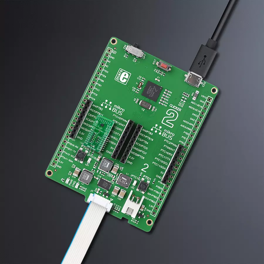
Clicker 2 for Kinetis is a compact starter development board that brings the flexibility of add-on Click boards™ to your favorite microcontroller, making it a perfect starter kit for implementing your ideas. It comes with an onboard 32-bit ARM Cortex-M4F microcontroller, the MK64FN1M0VDC12 from NXP Semiconductors, two mikroBUS™ sockets for Click board™ connectivity, a USB connector, LED indicators, buttons, a JTAG programmer connector, and two 26-pin headers for interfacing with external electronics. Its compact design with clear and easily recognizable silkscreen markings allows you to build gadgets with unique functionalities and
features quickly. Each part of the Clicker 2 for Kinetis development kit contains the components necessary for the most efficient operation of the same board. In addition to the possibility of choosing the Clicker 2 for Kinetis programming method, using a USB HID mikroBootloader or an external mikroProg connector for Kinetis programmer, the Clicker 2 board also includes a clean and regulated power supply module for the development kit. It provides two ways of board-powering; through the USB Micro-B cable, where onboard voltage regulators provide the appropriate voltage levels to each component on the board, or
using a Li-Polymer battery via an onboard battery connector. All communication methods that mikroBUS™ itself supports are on this board, including the well-established mikroBUS™ socket, reset button, and several user-configurable buttons and LED indicators. Clicker 2 for Kinetis is an integral part of the Mikroe ecosystem, allowing you to create a new application in minutes. Natively supported by Mikroe software tools, it covers many aspects of prototyping thanks to a considerable number of different Click boards™ (over a thousand boards), the number of which is growing every day.

Microcontroller Overview
MCU Card / MCU

Architecture
ARM Cortex-M4
MCU Memory (KB)
1024
Silicon Vendor
NXP
Pin count
121
RAM (Bytes)
262144
Used MCU Pins
mikroBUS™ mapper
Take a closer look
Click board™ Schematic

Step by step
Project assembly

Start by selecting your development board and Click board™. Begin with the Clicker 2 for Kinetis as your development board.


Track your results in real time
Application Output
1. Application Output - In Debug mode, the 'Application Output' window enables real-time data monitoring, offering direct insight into execution results. Ensure proper data display by configuring the environment correctly using the provided tutorial.

2. UART Terminal - Use the UART Terminal to monitor data transmission via a USB to UART converter, allowing direct communication between the Click board™ and your development system. Configure the baud rate and other serial settings according to your project's requirements to ensure proper functionality. For step-by-step setup instructions, refer to the provided tutorial.

3. Plot Output - The Plot feature offers a powerful way to visualize real-time sensor data, enabling trend analysis, debugging, and comparison of multiple data points. To set it up correctly, follow the provided tutorial, which includes a step-by-step example of using the Plot feature to display Click board™ readings. To use the Plot feature in your code, use the function: plot(*insert_graph_name*, variable_name);. This is a general format, and it is up to the user to replace 'insert_graph_name' with the actual graph name and 'variable_name' with the parameter to be displayed.

Software Support
Library Description
This library contains API for 9DOF 3 Click driver.
Key functions:
c9dof3_check_communication- This function check device ID for accelerometer, gyroscope and magnetometerc9dof3_get_data- This function read Accel, Gyro and Mag X-axis, Y-axis data and Z-axis datac9dof3_generic_read- This function reads data from the desired register
Open Source
Code example
The complete application code and a ready-to-use project are available through the NECTO Studio Package Manager for direct installation in the NECTO Studio. The application code can also be found on the MIKROE GitHub account.
/*!
 * \file
 * \brief 9Dof3 Click example
 *
 * # Description
 * This Click introduces a small-scale absolute orientation sensor in the class of low-noise
 * 9-axis measurement units. It comprises the full functionality of a triaxial, low-g acceleration
 * sensor, a triaxial angular rate sensor and a triaxial geomagnetic sensor. All three sensor
 * components can be operated and addressed independently from each other. 9DOF 3 Click offers
 * both SPI and I2C digital interfaces
 *
 * The demo application is composed of two sections :
 *
 * ## Application Init
 * Initialization driver enables - I2C or SPI, check communication,
 * set default configuration for accelerometer, gyroscope and magnetometer, also write log.
 *
 * ## Application Task
 * This is an example which demonstrates the use of 9DOF 3 Click board.
 * Measures and displays Accel, Gyroscope and Magnetometer values for X-axis, Y-axis and Z-axis.
 * Results are being sent to the Usart Terminal where you can track their changes.
 * All data logs write on USB uart changes for every 1 sec.
 *
 * \author MikroE Team
 *
 */
// ------------------------------------------------------------------- INCLUDES

#include "board.h"
#include "log.h"
#include "c9dof3.h"

// ------------------------------------------------------------------ VARIABLES

static c9dof3_t c9dof3;
static log_t logger;

c9dof3_accel_t accel_data;
c9dof3_gyro_t gyro_data;
c9dof3_mag_t mag_data;

// ------------------------------------------------------ APPLICATION FUNCTIONS

void application_init ( void )
{
    log_cfg_t log_cfg;
    c9dof3_cfg_t cfg;

    /**
     * Logger initialization.
     * Default baud rate: 115200
     * Default log level: LOG_LEVEL_DEBUG
     * @note If USB_UART_RX and USB_UART_TX
     * are defined as HAL_PIN_NC, you will
     * need to define them manually for log to work.
     * See @b LOG_MAP_USB_UART macro definition for detailed explanation.
     */
    LOG_MAP_USB_UART( log_cfg );
    log_init( &logger, &log_cfg );
    log_info( &logger, "---- Application Init ----" );

    //  Click initialization.

    c9dof3_cfg_setup( &cfg );
    C9DOF3_MAP_MIKROBUS( cfg, MIKROBUS_1 );
    c9dof3_init( &c9dof3, &cfg );
    Delay_ms ( 100 );

    if ( c9dof3_check_communication( &c9dof3 ) == ( C9DOF3_ACC_COMM_SUCCESS  |
                                                    C9DOF3_GYRO_COMM_SUCCESS |
                                                    C9DOF3_MAG_COMM_SUCCESS ) )
    {
        log_printf( &logger, "    Communication OK     \r\n" );
    }
    else
    {
        log_printf( &logger, "   Communication ERROR   \r\n" );
        log_printf( &logger, "     Reset the device    \r\n" );
        log_printf( &logger, "-------------------------\r\n" );
        for ( ; ; );
    }

    log_printf( &logger, "-------------------------\r\n" );
    c9dof3_default_cfg( &c9dof3 );
    Delay_ms ( 100 );
}

void application_task ( void )
{
    c9dof3_get_data ( &c9dof3, &accel_data, &gyro_data, &mag_data );

    log_printf( &logger, " Accel X: %d | Gyro X: %d |  Mag X: %d\r\n", accel_data.x, gyro_data.x, mag_data.x );
    log_printf( &logger, " Accel Y: %d | Gyro Y: %d |  Mag Y: %d\r\n", accel_data.y, gyro_data.y, mag_data.y );
    log_printf( &logger, " Accel Z: %d | Gyro Z: %d |  Mag Z: %d\r\n", accel_data.z, gyro_data.z, mag_data.z );

    log_printf( &logger, "------------------------------------------\r\n" );

    Delay_ms ( 1000 );
}

int main ( void )
{
    /* Do not remove this line or clock might not be set correctly. */
    #ifdef PREINIT_SUPPORTED
    preinit();
    #endif

    application_init( );

    for ( ; ; )
    {
        application_task( );
    }

    return 0;
}


// ------------------------------------------------------------------------ END


