Implement iButton™ technology into your projects with CZ-0-PIN and MK64FN1M0VDC12
Secure and reliable data transfer with a simple touch

Published Mar 15, 2024
Click board™
iButton Click
Dev. board
Clicker 2 for Kinetis
Compiler
NECTO Studio
MCU
MK64FN1M0VDC12
Create systems that require secure, physical touchpoints for data transfer or user identification
A
A
Hardware Overview
How does it work?
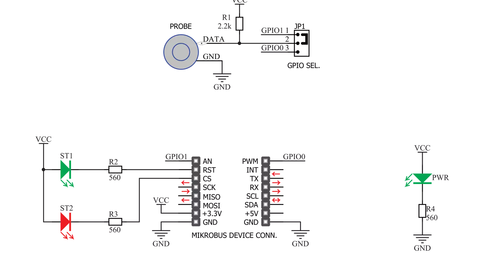
iButton Click is based on the CZ-0-PIN, a high-quality iButton probe from Demiurge. The metal probe ensures resistance to dirt, dust, moisture, shock, and other environmental hazards while ensuring good alignment with the iButton device. The manufacturer guarantees compatibility with Analog iButton devices, but the probe can read any other device compatible with the maxim iButton. The iButton device can power itself up through the data line by employing the so-called parasite power supply. This Click board™ is equipped with the pull-up resistor to the 3.3V mikroBUS™ rail, providing power for the iButton. The so-called parasite PSU of the iButton contains an internal capacitor, which
provides enough current for the proper operation once the data line has charged. To allow proper functioning of the parasitic PSU, the idle state of the data line is HIGH, while the data line of the iButton device is in an open-drain configuration, pulling the data line to a LOW logic level when asserted. The 1-Wire communication line is routed to the SMD jumper, which allows routing of the 1-Wire communication either to the PWM pin or to the AN pin of the mikroBUS™. These pins are labeled GP0 and GP1, respectively, the same as the SMD jumper positions, making the selection of the desired pin simple and straightforward. The green LED labeled as ST1 is routed to the RST pin of the
mikroBUS™, while the red LED is labeled as ST2 and is routed to the CS pin of the mikroBUS™. These two pins allow visual feedback from the software; for example, if the serial number of the docked iButton matches the authorization criteria, the green LED can signal it. These LEDs can be used for any signalization and are not directly connected to the iButton device. This Click board™ can be operated only with a 3.3V logic voltage level. The board must perform appropriate logic voltage level conversion before using MCUs with different logic levels. Also, it comes equipped with a library containing functions and an example code that can be used for further development.

Features overview
Development board
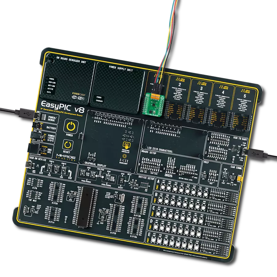
Clicker 2 for Kinetis is a compact starter development board that brings the flexibility of add-on Click boards™ to your favorite microcontroller, making it a perfect starter kit for implementing your ideas. It comes with an onboard 32-bit ARM Cortex-M4F microcontroller, the MK64FN1M0VDC12 from NXP Semiconductors, two mikroBUS™ sockets for Click board™ connectivity, a USB connector, LED indicators, buttons, a JTAG programmer connector, and two 26-pin headers for interfacing with external electronics. Its compact design with clear and easily recognizable silkscreen markings allows you to build gadgets with unique functionalities and
features quickly. Each part of the Clicker 2 for Kinetis development kit contains the components necessary for the most efficient operation of the same board. In addition to the possibility of choosing the Clicker 2 for Kinetis programming method, using a USB HID mikroBootloader or an external mikroProg connector for Kinetis programmer, the Clicker 2 board also includes a clean and regulated power supply module for the development kit. It provides two ways of board-powering; through the USB Micro-B cable, where onboard voltage regulators provide the appropriate voltage levels to each component on the board, or
using a Li-Polymer battery via an onboard battery connector. All communication methods that mikroBUS™ itself supports are on this board, including the well-established mikroBUS™ socket, reset button, and several user-configurable buttons and LED indicators. Clicker 2 for Kinetis is an integral part of the Mikroe ecosystem, allowing you to create a new application in minutes. Natively supported by Mikroe software tools, it covers many aspects of prototyping thanks to a considerable number of different Click boards™ (over a thousand boards), the number of which is growing every day.

Microcontroller Overview
MCU Card / MCU

Architecture
ARM Cortex-M4
MCU Memory (KB)
1024
Silicon Vendor
NXP
Pin count
121
RAM (Bytes)
262144
You complete me!
Accessories
The DS1990A is a unique serial number identification iButton™. The iButton is a technology based on the one-wire communication protocol and a chip packed in a robust stainless steel casing. This button-shaped device has two contacts - the lid and the base. These contacts carry the necessary connections down to a sensitive silicone chip embedded inside the metal button. When the iButton touches the reader probe, it establishes the communication with the host MCU via the one-wire interface. The communication is almost instant, so pressing the iButton lightly to the probe contacts is enough.

Used MCU Pins
mikroBUS™ mapper
Take a closer look
Click board™ Schematic
Step by step
Project assembly

Start by selecting your development board and Click board™. Begin with the Clicker 2 for Kinetis as your development board.


Software Support
Library Description
This library contains API for iButton Click driver.
Key functions:
ibutton_add_key- This function reads the ROM address from a DS1990A Serial Number iButton and stores it in the ctx->key_rom buffeributton_remove_keys- This function removes all stored keys by clearing the ctx->key_rom buffeributton_check_key- This function reads the ROM address from a DS1990A Serial Number iButton and checks if it is already stored in the ctx->key_rom buffer
Open Source
Code example
The complete application code and a ready-to-use project are available through the NECTO Studio Package Manager for direct installation in the NECTO Studio. The application code can also be found on the MIKROE GitHub account.
/*!
 * @file main.c
 * @brief iButton Click Example.
 *
 * # Description
 * This example demonstrates the use of the iButton Click boards by registering a DS1990A Serial Number iButton
 * key and then waiting until a key is detected on the reader and identifying if the key matches one of
 * those stored in RAM.
 *
 * The demo application is composed of two sections :
 *
 * ## Application Init
 * Initializes the driver and registers a new DS1990A Serial Number iButton key and stores it in RAM.
 *
 * ## Application Task
 * Waits until a key is detected on the reader, and checks if there's a key found in the library that matches
 * the one it has just read. All data is being logged on the USB UART where you can track the program flow.
 *
 * @author Stefan Filipovic
 *
 */

#include "board.h"
#include "log.h"
#include "ibutton.h"

#define NUMBER_OF_KEYS  1   // Number of keys to register.

static ibutton_t ibutton;
static log_t logger;

/**
 * @brief iButton led indication function.
 * @details This function indicates the selected state over LEDs indication.
 * @param[in] ctx : Click context object.
 * See #ibutton_t object definition for detailed explanation.
 * @param[in] state : @li @c 0 - Disable LEDs.
 *                    @li @c 1 - Wait for a key.
 *                    @li @c 2 - Operation successfull.
 *                    @li @c 3 - Wrong key found.
 * @return None.
 * @note None.
 */
static void ibutton_led_indication ( ibutton_t *ctx, ibutton_led_state_t state );

/**
 * @brief iButton register keys function.
 * @details This function registers a desired number of keys.
 * Each step will be logged on the USB UART where you can track the function flow.
 * @param[in] ctx : Click context object.
 * See #ibutton_t object definition for detailed explanation.
 * @param[in] num_keys : Number of keys to register.
 * @return None.
 * @note None.
 */
static void ibutton_register_keys ( ibutton_t *ctx, uint8_t num_keys );

void application_init ( void )
{
    log_cfg_t log_cfg;  /**< Logger config object. */
    ibutton_cfg_t ibutton_cfg;  /**< Click config object. */

    /**
     * Logger initialization.
     * Default baud rate: 115200
     * Default log level: LOG_LEVEL_DEBUG
     * @note If USB_UART_RX and USB_UART_TX
     * are defined as HAL_PIN_NC, you will
     * need to define them manually for log to work.
     * See @b LOG_MAP_USB_UART macro definition for detailed explanation.
     */
    LOG_MAP_USB_UART( log_cfg );
    log_init( &logger, &log_cfg );
    log_info( &logger, " Application Init " );

    // Click initialization.
    ibutton_cfg_setup( &ibutton_cfg );
    IBUTTON_MAP_MIKROBUS( ibutton_cfg, MIKROBUS_1 );
    if ( ONE_WIRE_ERROR == ibutton_init( &ibutton, &ibutton_cfg ) )
    {
        log_error( &logger, " Communication init." );
        for ( ; ; );
    }

    ibutton_register_keys ( &ibutton, NUMBER_OF_KEYS );

    log_info( &logger, " Application Task " );
}

void application_task ( void )
{
    err_t error_flag = IBUTTON_OK;
    ibutton_led_indication ( &ibutton, IBUTTON_LED_DISABLE );
    log_printf( &logger, " >>> Waiting for a key <<<\r\n" );
    do
    {
        ibutton_led_indication ( &ibutton, IBUTTON_LED_WAIT_KEY );
        error_flag = ibutton_check_key ( &ibutton );
    }
    while ( IBUTTON_ERROR == error_flag );

    ibutton_led_indication ( &ibutton, IBUTTON_LED_DISABLE );
    if ( IBUTTON_OK == error_flag )
    {
        log_printf( &logger, " MATCH, access allowed!\r\n" );
        ibutton_led_indication ( &ibutton, IBUTTON_LED_SUCCESS );
    }
    else if ( IBUTTON_KEY_NO_MATCH == error_flag )
    {
        log_printf( &logger, " NO MATCH, access denied!\r\n" );
        ibutton_led_indication ( &ibutton, IBUTTON_LED_WRONG_KEY );
    }
    ibutton_led_indication ( &ibutton, IBUTTON_LED_DISABLE );
    log_printf( &logger, "--------------------------------\r\n\n" );
    Delay_ms ( 500 );
}

int main ( void )
{
    /* Do not remove this line or clock might not be set correctly. */
    #ifdef PREINIT_SUPPORTED
    preinit();
    #endif

    application_init( );

    for ( ; ; )
    {
        application_task( );
    }

    return 0;
}

static void ibutton_led_indication ( ibutton_t *ctx, ibutton_led_state_t state )
{
    switch ( state )
    {
        case IBUTTON_LED_DISABLE:
        {
            ibutton_disable_green_led ( ctx );
            ibutton_disable_red_led ( ctx );
            break;
        }
        case IBUTTON_LED_WAIT_KEY:
        {
            ibutton_enable_green_led ( &ibutton );
            Delay_ms ( 250 );
            ibutton_disable_green_led ( &ibutton );
            ibutton_enable_red_led ( &ibutton );
            Delay_ms ( 250 );
            ibutton_disable_red_led ( &ibutton );
            break;
        }
        case IBUTTON_LED_SUCCESS:
        {
            ibutton_enable_green_led ( &ibutton );
            Delay_ms ( 250 );
            ibutton_disable_green_led ( &ibutton );
            Delay_ms ( 250 );
            ibutton_enable_green_led ( &ibutton );
            Delay_ms ( 250 );
            ibutton_disable_green_led ( &ibutton );
            Delay_ms ( 250 );
            break;
        }
        case IBUTTON_LED_WRONG_KEY:
        {
            ibutton_enable_red_led ( &ibutton );
            Delay_ms ( 250 );
            ibutton_disable_red_led ( &ibutton );
            Delay_ms ( 250 );
            ibutton_enable_red_led ( &ibutton );
            Delay_ms ( 250 );
            ibutton_disable_red_led ( &ibutton );
            Delay_ms ( 250 );
            break;
        }
        default:
        {
            break;
        }
    }
}

static void ibutton_register_keys ( ibutton_t *ctx, uint8_t num_keys )
{
    err_t error_flag = IBUTTON_OK;
    uint8_t key_cnt = 1;
    while ( key_cnt <= num_keys )
    {
        ibutton_led_indication ( &ibutton, IBUTTON_LED_DISABLE );
        log_printf( &logger, " >>> Registering key %u of %u <<<\r\n", ( uint16_t ) key_cnt, ( uint16_t ) num_keys );
        log_printf( &logger, " Insert a DS1990A Serial Number iButton to Click board reader plate\r\n" );
        do
        {
            ibutton_led_indication ( &ibutton, IBUTTON_LED_WAIT_KEY );
            error_flag = ibutton_add_key ( &ibutton );
        }
        while ( IBUTTON_ERROR == error_flag );

        ibutton_led_indication ( &ibutton, IBUTTON_LED_DISABLE );
        if ( IBUTTON_KEY_ALREADY_EXIST == error_flag )
        {
            log_printf( &logger, " This key is already registered!\r\n" );
            log_printf( &logger, " Use another key or decrease the number of keys\r\n" );
            ibutton_led_indication ( &ibutton, IBUTTON_LED_WRONG_KEY );
        }
        else if ( IBUTTON_OK == error_flag )
        {
            log_printf( &logger, " The key is registered successfully!\r\n" );
            ibutton_led_indication ( &ibutton, IBUTTON_LED_SUCCESS );
            key_cnt++;
        }
        ibutton_led_indication ( &ibutton, IBUTTON_LED_DISABLE );
        log_printf( &logger, "--------------------------------\r\n\n" );
        Delay_ms ( 500 );
    }
}

// ------------------------------------------------------------------------ END
Additional Support
Resources
Category:1-Wire