Deliver precise electrical isolation and signal conditioning with DCL540C01 and MK64FN1M0VDC12
Explore the future of industrial automation and beyond.

Published Nov 15, 2023
Click board™
DIGI Isolator Click
Dev. board
Clicker 2 for Kinetis
Compiler
NECTO Studio
MCU
MK64FN1M0VDC12
Perfect solution for developers pushing the boundaries in industrial automation, motor control, inverters, and more. Experience enhanced SPI and UART interface isolation where it matters.
A
A
Hardware Overview
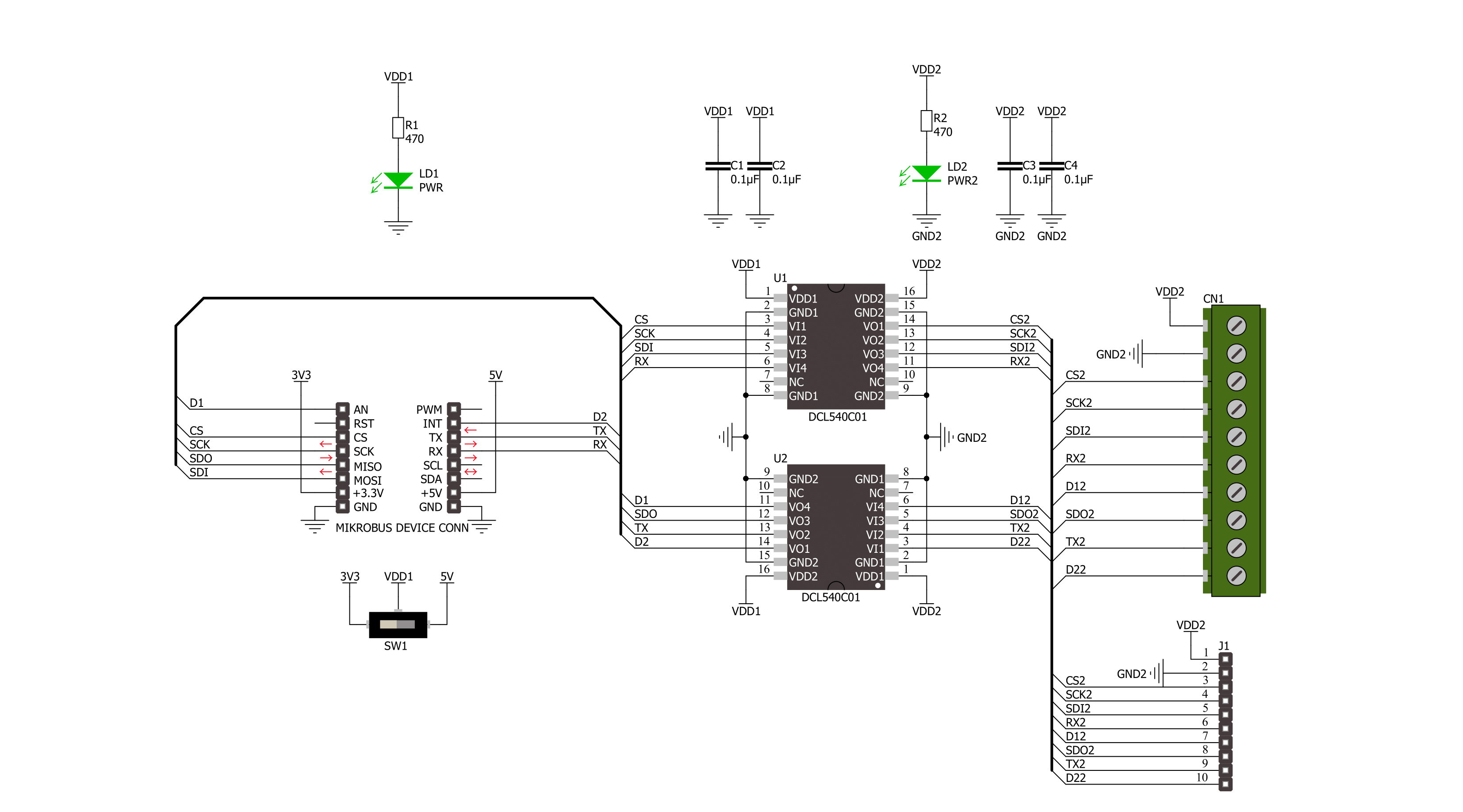
How does it work?
DIGI Isolator Click is based on two DCL540C01, high-speed, quad-channel digital isolators from Toshiba Semiconductor. Toshiba used the magnetic coupling structure and CMOS technology to achieve high reinforced isolation. The isolated lines are divided into two electrically connected groups. The first group comes in the form of 8 screw terminals, while the second forms a classic male 10-header row for easier jumper wire usage. Both groups of connectors have the same functions and are labeled the same. You can
distinguish the power VDD2 and GND2 lines from the data lines: four SPI, UART TX/RX, and two digital IO lines. The isolator can work with supply voltages from 2.25 up to 5.5V. DIGI Isolator Click uses standard 4-Wire SPI serial interface lines, standard UART TX/RX interface lines, and two additional GP lines from the mikroBUS™ socket as an insulated extension, marked D2 and D1, respectively. The SPI and UART pins are labeled according to the standard interface markings. These eight lines go through the DCL540C01s to
the terminals and headers, thus isolating the host MCU from the connected device. This Click board™ can operate with either 3.3V or 5V logic voltage levels selected via the VCC SEL switch. This way, both 3.3V and 5V capable MCUs can use the communication lines properly. Also, this Click board™ comes equipped with a library containing easy-to-use functions and an example code that can be used as a reference for further development.

Features overview
Development board
Clicker 2 for Kinetis is a compact starter development board that brings the flexibility of add-on Click boards™ to your favorite microcontroller, making it a perfect starter kit for implementing your ideas. It comes with an onboard 32-bit ARM Cortex-M4F microcontroller, the MK64FN1M0VDC12 from NXP Semiconductors, two mikroBUS™ sockets for Click board™ connectivity, a USB connector, LED indicators, buttons, a JTAG programmer connector, and two 26-pin headers for interfacing with external electronics. Its compact design with clear and easily recognizable silkscreen markings allows you to build gadgets with unique functionalities and
features quickly. Each part of the Clicker 2 for Kinetis development kit contains the components necessary for the most efficient operation of the same board. In addition to the possibility of choosing the Clicker 2 for Kinetis programming method, using a USB HID mikroBootloader or an external mikroProg connector for Kinetis programmer, the Clicker 2 board also includes a clean and regulated power supply module for the development kit. It provides two ways of board-powering; through the USB Micro-B cable, where onboard voltage regulators provide the appropriate voltage levels to each component on the board, or
using a Li-Polymer battery via an onboard battery connector. All communication methods that mikroBUS™ itself supports are on this board, including the well-established mikroBUS™ socket, reset button, and several user-configurable buttons and LED indicators. Clicker 2 for Kinetis is an integral part of the Mikroe ecosystem, allowing you to create a new application in minutes. Natively supported by Mikroe software tools, it covers many aspects of prototyping thanks to a considerable number of different Click boards™ (over a thousand boards), the number of which is growing every day.

Microcontroller Overview
MCU Card / MCU

Architecture
ARM Cortex-M4
MCU Memory (KB)
1024
Silicon Vendor
NXP
Pin count
121
RAM (Bytes)
262144
Used MCU Pins
mikroBUS™ mapper
Take a closer look
Click board™ Schematic
Step by step
Project assembly

Start by selecting your development board and Click board™. Begin with the Clicker 2 for Kinetis as your development board.


Software Support
Library Description
This library contains API for DIGI Isolator Click driver.
Key functions:
digiisolator_spi_transfer- DIGI Isolator SPI transfer function.digiisolator_uart_write- DIGI Isolator UART data writing functiondigiisolator_get_d1_pin_voltage- DIGI Isolator read D1 pin voltage level function.
Open Source
Code example
The complete application code and a ready-to-use project are available through the NECTO Studio Package Manager for direct installation in the NECTO Studio. The application code can also be found on the MIKROE GitHub account.
/*!
 * @file main.c
 * @brief DIGI Isolator Click example
 *
 * # Description
 * This example demonstrates the use of the DIGI Isolator Click board
 * by reading and writing data by using SPI and UART serial interface
 * and reading results of AD conversion.
 *
 * The demo application is composed of two sections :
 *
 * ## Application Init
 * Initialization of SPI, UART and ADC module and log UART.
 *
 * ## Application Task
 * At the start, the demo application reads and checks the manufacturer ID and
 * device ID of the connected Flash 11 Click board by using SPI serial interface.
 * After that, sends a "MikroE" message, reads the received data,
 * and parses it by using UART serial interface in loopback mode.
 * And finally, the demo app reads the results of the AD conversion of the D1 (AN) pin.
 * Results are being sent to the UART Terminal, where you can track their changes.
 *
 * @author Nenad Filipovic
 *
 */

#include "board.h"
#include "log.h"
#include "digiisolator.h"

#define FLASH11_CMD_GET_ID         0x90, 0x00, 0x00, 0x00, 0x00, 0x00
#define FLASH11_MANUFACTURER_ID    0x1F
#define FLASH11_DEVICE_ID          0x15
#define DEMO_MESSAGE               "\r\nMikroE\r\n"
#define PROCESS_BUFFER_SIZE        200

static digiisolator_t digiisolator;
static log_t logger;

void application_init ( void )
{
    log_cfg_t log_cfg;  /**< Logger config object. */
    digiisolator_cfg_t digiisolator_cfg;  /**< Click config object. */

    /**
     * Logger initialization.
     * Default baud rate: 115200
     * Default log level: LOG_LEVEL_DEBUG
     * @note If USB_UART_RX and USB_UART_TX
     * are defined as HAL_PIN_NC, you will
     * need to define them manually for log to work.
     * See @b LOG_MAP_USB_UART macro definition for detailed explanation.
     */
    LOG_MAP_USB_UART( log_cfg );
    log_init( &logger, &log_cfg );
    log_info( &logger, " Application Init " );

    // Click initialization.
    digiisolator_cfg_setup( &digiisolator_cfg );
    DIGIISOLATOR_MAP_MIKROBUS( digiisolator_cfg, MIKROBUS_1 );
    if ( SPI_MASTER_ERROR == digiisolator_init( &digiisolator, &digiisolator_cfg ) )
    {
        log_error( &logger, " Communication init." );
        for ( ; ; );
    }

    log_info( &logger, " Application Task " );
    log_printf( &logger, " -----------------------\r\n" );
    Delay_ms ( 100 );
}

void application_task ( void )
{
    static uint8_t cmd_get_id[ 6 ] = { FLASH11_CMD_GET_ID };
    static uint8_t read_id[ 6 ] = { 0 };
    static char app_buf[ PROCESS_BUFFER_SIZE ] = { 0 };
    static float voltage = 0;

    if ( DIGIISOLATOR_OK == digiisolator_spi_transfer( &digiisolator, &cmd_get_id[ 0 ], &read_id[ 0 ], 6 ) )
    {
        if ( ( FLASH11_MANUFACTURER_ID == read_id[ 4 ] ) && ( FLASH11_DEVICE_ID == read_id[ 5 ] ) )
        {
            log_printf( &logger, " SPI\r\n" );
            log_printf( &logger, " Manufacturer ID: 0x%.2X\r\n", ( uint16_t ) read_id[ 4 ] );
            log_printf( &logger, " Device ID: 0x%.2X    \r\n", ( uint16_t ) read_id[ 5 ] );
            log_printf( &logger, " -----------------------\r\n" );
            Delay_ms ( 1000 );
            Delay_ms ( 1000 );
        }
    }

    if ( 0 < digiisolator_uart_write( &digiisolator, DEMO_MESSAGE, strlen( DEMO_MESSAGE ) ) )
    {
        if ( 0 < digiisolator_uart_read( &digiisolator, app_buf, strlen( DEMO_MESSAGE ) ) )
        {
            log_printf( &logger, " UART\r\n" );
            log_printf( &logger, "%s", app_buf );
            memset( app_buf, 0, PROCESS_BUFFER_SIZE );
            log_printf( &logger, " -----------------------\r\n" );
            Delay_ms ( 1000 );
            Delay_ms ( 1000 );
        }
    }

    if ( DIGIISOLATOR_OK == digiisolator_get_d1_pin_voltage ( &digiisolator, &voltage ) )
    {
        log_printf( &logger, " ADC\r\n" );
        log_printf( &logger, " Voltage : %.3f[V]\r\n", voltage );
        log_printf( &logger, " -----------------------\r\n" );
        Delay_ms ( 1000 );
        Delay_ms ( 1000 );
    }
}

int main ( void )
{
    /* Do not remove this line or clock might not be set correctly. */
    #ifdef PREINIT_SUPPORTED
    preinit();
    #endif

    application_init( );

    for ( ; ; )
    {
        application_task( );
    }

    return 0;
}

// ------------------------------------------------------------------------ END


