Simplify water presence monitoring with MCP606 and MK64FN1M0VDC12
Monitor water intrusion for peace of mind

Published Oct 02, 2023
Click board™
Water Detect Click
Dev. board
Clicker 2 for Kinetis
Compiler
NECTO Studio
MCU
MK64FN1M0VDC12
The purpose of this solution is to offer reliable water detection, helping prevent water damage and mitigate potential risks in various environments
A
A
Hardware Overview
How does it work?
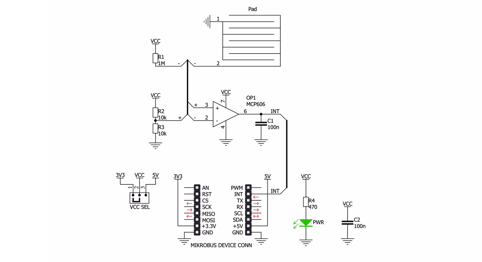
Water Detect Click is used for detecting water and other electroconductive liquids. If the detection area is wet the output of Microchip's MCP606 CMOS op-amp will go positive, signaling the presence of liquid. Water Detect click can be used as a household flood alarm sensor, rain detector for smart buildings or for water tanks that act as a limit switch for a pump. Water Detect click works by comparing the voltage of two resistor dividers using the MCP606 comparator. The resistor divider (made of R2 and R3) is used as a voltage reference. The MCP606 functions as a comparator on this
Click board™. The second divider is made of resistor R1 and the sensory area. When the sensory area is dry, it's resistance is near infinite, and the voltage applied to the inverting terminal of the comparator equals VCC. Since the voltage of the reference divider connected to the non-inverting input is VCC/2, the output of the comparator is at zero voltage. Once the liquid is present at the sensory area, it's resistance drops and pulls the voltage on the inverting input of the comparator toward zero volts. Once this voltage falls below VCC/2, the comparator output swings toward VCC
signaling the presence of liquid. The comparator output is tied to the INT pin on the mikroBUS™ header. The water detection area is actually made of exposed conducting wires - simple but effective technology. This Click board™ can operate with either 3.3V or 5V logic voltage levels selected via the VCC SEL jumper. This way, both 3.3V and 5V capable MCUs can use the communication lines properly. Also, this Click board™ comes equipped with a library containing easy-to-use functions and an example code that can be used as a reference for further development.


Features overview
Development board
Clicker 2 for Kinetis is a compact starter development board that brings the flexibility of add-on Click boards™ to your favorite microcontroller, making it a perfect starter kit for implementing your ideas. It comes with an onboard 32-bit ARM Cortex-M4F microcontroller, the MK64FN1M0VDC12 from NXP Semiconductors, two mikroBUS™ sockets for Click board™ connectivity, a USB connector, LED indicators, buttons, a JTAG programmer connector, and two 26-pin headers for interfacing with external electronics. Its compact design with clear and easily recognizable silkscreen markings allows you to build gadgets with unique functionalities and
features quickly. Each part of the Clicker 2 for Kinetis development kit contains the components necessary for the most efficient operation of the same board. In addition to the possibility of choosing the Clicker 2 for Kinetis programming method, using a USB HID mikroBootloader or an external mikroProg connector for Kinetis programmer, the Clicker 2 board also includes a clean and regulated power supply module for the development kit. It provides two ways of board-powering; through the USB Micro-B cable, where onboard voltage regulators provide the appropriate voltage levels to each component on the board, or
using a Li-Polymer battery via an onboard battery connector. All communication methods that mikroBUS™ itself supports are on this board, including the well-established mikroBUS™ socket, reset button, and several user-configurable buttons and LED indicators. Clicker 2 for Kinetis is an integral part of the Mikroe ecosystem, allowing you to create a new application in minutes. Natively supported by Mikroe software tools, it covers many aspects of prototyping thanks to a considerable number of different Click boards™ (over a thousand boards), the number of which is growing every day.

Microcontroller Overview
MCU Card / MCU

Architecture
ARM Cortex-M4
MCU Memory (KB)
1024
Silicon Vendor
NXP
Pin count
121
RAM (Bytes)
262144
Used MCU Pins
mikroBUS™ mapper
Take a closer look
Click board™ Schematic
Step by step
Project assembly

Start by selecting your development board and Click board™. Begin with the Clicker 2 for Kinetis as your development board.


Track your results in real time
Application Output
1. Application Output - In Debug mode, the 'Application Output' window enables real-time data monitoring, offering direct insight into execution results. Ensure proper data display by configuring the environment correctly using the provided tutorial.

2. UART Terminal - Use the UART Terminal to monitor data transmission via a USB to UART converter, allowing direct communication between the Click board™ and your development system. Configure the baud rate and other serial settings according to your project's requirements to ensure proper functionality. For step-by-step setup instructions, refer to the provided tutorial.

3. Plot Output - The Plot feature offers a powerful way to visualize real-time sensor data, enabling trend analysis, debugging, and comparison of multiple data points. To set it up correctly, follow the provided tutorial, which includes a step-by-step example of using the Plot feature to display Click board™ readings. To use the Plot feature in your code, use the function: plot(*insert_graph_name*, variable_name);. This is a general format, and it is up to the user to replace 'insert_graph_name' with the actual graph name and 'variable_name' with the parameter to be displayed.

Software Support
Library Description
This library contains API for Water DetectClick driver.
Key functions:
waterdetect_get_status- Get the status of the water detection function
Open Source
Code example
The complete application code and a ready-to-use project are available through the NECTO Studio Package Manager for direct installation in the NECTO Studio. The application code can also be found on the MIKROE GitHub account.
/*!
 * \file
 * \brief Water Detect Click example
 *
 * # Description
 * Water Detect Click is used for detecting water and other electroconductive liquids. If the detection area is wet the output of Microchip's MCP606 CMOS op-amp will go positive, signaling the presence of liquid.
 *
 * The demo application is composed of two sections :
 *
 * ## Application Init
 * Initializes GPIO and LOG structures, set INT pins as input and starts to write log.
 *
 * ## Application Task
 * Reads device status and determines if there are water presence or not.
 *
 * \author MikroE Team
 *
 */
// ------------------------------------------------------------------- INCLUDES

#include "board.h"
#include "log.h"
#include "waterdetect.h"

// ------------------------------------------------------------------ VARIABLES

static waterdetect_t waterdetect;
static log_t logger;

uint8_t wd_state = 0;
uint8_t wd_state_old = 0;

// ------------------------------------------------------ APPLICATION FUNCTIONS

void application_init ( void )
{
    log_cfg_t log_cfg;
    waterdetect_cfg_t cfg;

    /**
     * Logger initialization.
     * Default baud rate: 115200
     * Default log level: LOG_LEVEL_DEBUG
     * @note If USB_UART_RX and USB_UART_TX
     * are defined as HAL_PIN_NC, you will
     * need to define them manually for log to work.
     * See @b LOG_MAP_USB_UART macro definition for detailed explanation.
     */
    LOG_MAP_USB_UART( log_cfg );
    log_init( &logger, &log_cfg );
    log_info(&logger, "---- Application Init ----");

    //  Click initialization.

    waterdetect_cfg_setup( &cfg );
    WATERDETECT_MAP_MIKROBUS( cfg, MIKROBUS_1 );
    waterdetect_init( &waterdetect, &cfg );
    Delay_100ms();

    log_printf( &logger, "  Initialization Driver   \r\n" );
    log_printf( &logger, "------------------------- \r\n" );
    log_printf( &logger, "  Wait to detect water... \r\n" );
    log_printf( &logger, "------------------------- \r\n" );
}

void application_task ( void )
{
    wd_state = waterdetect_get_status( &waterdetect );

    if ( wd_state > wd_state_old )
    {
        log_printf( &logger, " >  Water is detected  < \r\n" );
        log_printf( &logger, "------------------------- \r\n" );
        wd_state_old = 1;
    }

    if ( wd_state < wd_state_old )
    {
        log_printf( &logger, " There is no water \r\n" );
        log_printf( &logger, "------------------- \r\n" );
        wd_state_old = 0;
    }
}

int main ( void )
{
    /* Do not remove this line or clock might not be set correctly. */
    #ifdef PREINIT_SUPPORTED
    preinit();
    #endif

    application_init( );

    for ( ; ; )
    {
        application_task( );
    }

    return 0;
}

// ------------------------------------------------------------------------ END


