Achieve electrical isolation in various high-voltage applications with VO2630 and PIC32MZ2048EFM100
No shocks, all safety!

Published Jan 24, 2024
Click board™
OPTO Click
Dev. board
Curiosity PIC32 MZ EF
Compiler
NECTO Studio
MCU
PIC32MZ2048EFM100
Provide electrical isolation from high voltage between input and output circuits in various applications, particularly where high-speed data transfer and a wide temperature range are important considerations
A
A
Hardware Overview
How does it work?
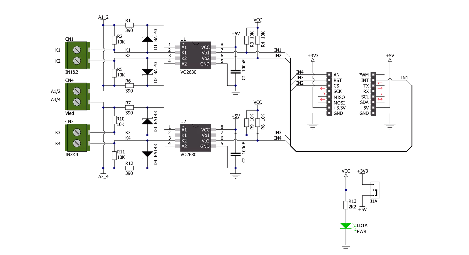
Opto Click is based on a double pack of the DIP socket VO2630, dual-channel, high-speed optocoupler modules from Vishay Semiconductors, providing electrical isolation between the input and output source. The VO2630 enables a high speed of 10Mbit/s data transfer between its input and output with galvanic isolation utilizing a highly efficient input LED coupled with an integrated optical photodiode detector. The detector has an open drain NMOS-transistor output, providing less
leakage than an open collector Schottky clamped transistor output. The VO2630 works like a switch connecting two isolated circuits, so when the current stops flowing through the LED, the photosensitive device stops conducting and turns off. It guarantees AC and DC performance withstanding 5300Vrms of isolation voltage over a wide temperature range from -40°C to +100°C. The outputs of the optocouplers are connected to four pins of the mikroBUS™ labeled IN1-IN4 and routed
to the INT, CS, RST, and AN pins of the mikroBUS™ socket. This Click board™ can operate with either 3.3V or 5V logic voltage levels selected via the I/O Level jumper. This way, both 3.3V and 5V capable MCUs can use the communication lines properly. Also, this Click board™ comes equipped with a library containing easy-to-use functions and an example code that can be used as a reference for further development.

Features overview
Development board
Curiosity PIC32 MZ EF development board is a fully integrated 32-bit development platform featuring the high-performance PIC32MZ EF Series (PIC32MZ2048EFM) that has a 2MB Flash, 512KB RAM, integrated FPU, Crypto accelerator, and excellent connectivity options. It includes an integrated programmer and debugger, requiring no additional hardware. Users can expand
functionality through MIKROE mikroBUS™ Click™ adapter boards, add Ethernet connectivity with the Microchip PHY daughter board, add WiFi connectivity capability using the Microchip expansions boards, and add audio input and output capability with Microchip audio daughter boards. These boards are fully integrated into PIC32’s powerful software framework, MPLAB Harmony,
which provides a flexible and modular interface to application development a rich set of inter-operable software stacks (TCP-IP, USB), and easy-to-use features. The Curiosity PIC32 MZ EF development board offers expansion capabilities making it an excellent choice for a rapid prototyping board in Connectivity, IOT, and general-purpose applications.

Microcontroller Overview
MCU Card / MCU

Architecture
PIC32
MCU Memory (KB)
2048
Silicon Vendor
Microchip
Pin count
100
RAM (Bytes)
524288
Used MCU Pins
mikroBUS™ mapper
Take a closer look
Click board™ Schematic
Step by step
Project assembly

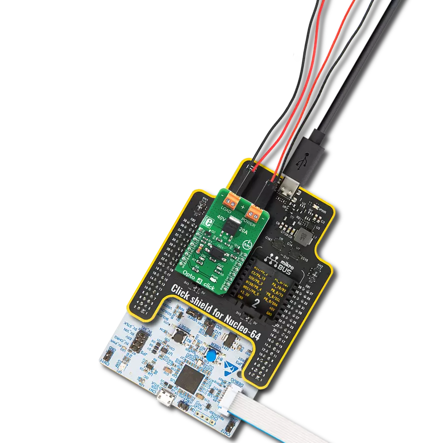
Start by selecting your development board and Click board™. Begin with the Curiosity PIC32 MZ EF as your development board.


Software Support
Library Description
This library contains API for OPTO Click driver.
Key functions:
opto_check_out1- This function checks the state of OUT1 pinopto_check_out2- This function checks the state of OUT2 pinopto_check_out3- This function checks the state of OUT3 pinopto_check_out4- This function checks the state of OUT4 pin
Open Source
Code example
The complete application code and a ready-to-use project are available through the NECTO Studio Package Manager for direct installation in the NECTO Studio. The application code can also be found on the MIKROE GitHub account.
/*!
 * \file
 * \brief OPTO Click example
 *
 * # Description
 * This application checks the state of selected inputs and prints it.
 *
 * The demo application is composed of two sections :
 *
 * ## Application Init
 * Initialization driver enables GPIO and also starts write log.
 *
 * ## Application Task
 * This example demonstrates the use of OPTO Click board by performing
 * the check procedure for selected outputs and displays the results on USART terminal.
 *
 *
 * \author MikroE Team
 *
 */
// ------------------------------------------------------------------- INCLUDES

#include "board.h"
#include "log.h"
#include "opto.h"

// ------------------------------------------------------------------ VARIABLES

static opto_t opto;
static log_t logger;
uint8_t sel_output;
uint8_t check_output;
uint8_t cnt;
uint8_t tmp;
// ------------------------------------------------------- ADDITIONAL FUNCTIONS

void opto_set_logger( uint8_t sel_out1, uint8_t sel_out2, uint8_t sel_out3, uint8_t sel_out4 )
{
    if ( sel_out1 > 1 )
    {
        sel_out1 = 1;
    }
    if ( sel_out2 > 1 )
    {
        sel_out2 = 1;
    }
    if ( sel_out3 > 1 )
    {
        sel_out3 = 1;
    }
    if ( sel_out4 > 1 )
    {
        sel_out4 = 1;
    }

    sel_output = 0;
    sel_output |= sel_out1;
    sel_output |= sel_out2 << 1;
    sel_output |= sel_out3 << 2;
    sel_output |= sel_out4 << 3;
}

// ------------------------------------------------------ APPLICATION FUNCTIONS

void application_init ( void )
{
    log_cfg_t log_cfg;
    opto_cfg_t cfg;

    /**
     * Logger initialization.
     * Default baud rate: 115200
     * Default log level: LOG_LEVEL_DEBUG
     * @note If USB_UART_RX and USB_UART_TX
     * are defined as HAL_PIN_NC, you will
     * need to define them manually for log to work.
     * See @b LOG_MAP_USB_UART macro definition for detailed explanation.
     */
    LOG_MAP_USB_UART( log_cfg );
    log_init( &logger, &log_cfg );
    log_info(&logger, "---- Application Init ----");

    //  Click initialization.

    opto_cfg_setup( &cfg );
    OPTO_MAP_MIKROBUS( cfg, MIKROBUS_1 );
    opto_init( &opto, &cfg );
    opto_set_logger(1,1,1,1);
}

void application_task ( void )
{
    tmp = 1;

    for( cnt = 0; cnt < 4; cnt++ )
    {
        switch( sel_output & tmp )
        {
            case 0x01 :
            {
                check_output = opto_check_out1( &opto );

                if( check_output == 0 )
                {
                    log_printf( &logger, "OUT1 is low\r\n" );
                }
                else
                {
                    log_printf( &logger, "OUT1 is high\r\n" );
                }
            break;
            }
            case 0x02 :
            {
                check_output = opto_check_out2( &opto );

                if ( check_output == 0 )
                {
                    log_printf( &logger, "OUT2 is low\r\n" );
                }
                else
                {
                    log_printf( &logger, "OUT2 is high\r\n" );
                }
            break;
            }
            case 0x04 :
            {
                check_output = opto_check_out3( &opto );

                if ( check_output == 0 )
                {
                    log_printf( &logger, "OUT3 is low\r\n" );
                }
                else
                {
                    log_printf( &logger, "OUT3 is high\r\n" );
                }
            break;
            }
            case 0x08 :
            {
                check_output = opto_check_out4( &opto );

                if ( check_output == 0 )
                {
                    log_printf( &logger, "OUT4 is low\r\n" );
                }
                else
                {
                    log_printf( &logger, "OUT4 is high\r\n" );
                }
            break;
            }
            default :
            {
            break;
            }
        }

        tmp <<= 1;
    }
    Delay_ms ( 1000 );
    Delay_ms ( 1000 );
}

int main ( void )
{
    /* Do not remove this line or clock might not be set correctly. */
    #ifdef PREINIT_SUPPORTED
    preinit();
    #endif

    application_init( );

    for ( ; ; )
    {
        application_task( );
    }

    return 0;
}


// ------------------------------------------------------------------------ END
Additional Support
Resources
Category:Optocoupler