Create a secure and distinctive digital identity using DS2401 and STM32L4A6RG
Your ID, your signature!

Published Jun 21, 2023
Click board™
UNIQUE ID Click
Dev. board
UNI Clicker
Compiler
NECTO Studio
MCU
STM32L4A6RG
Unlock a world of possibilities with your personalized digital ID!
A
A
Hardware Overview
How does it work?
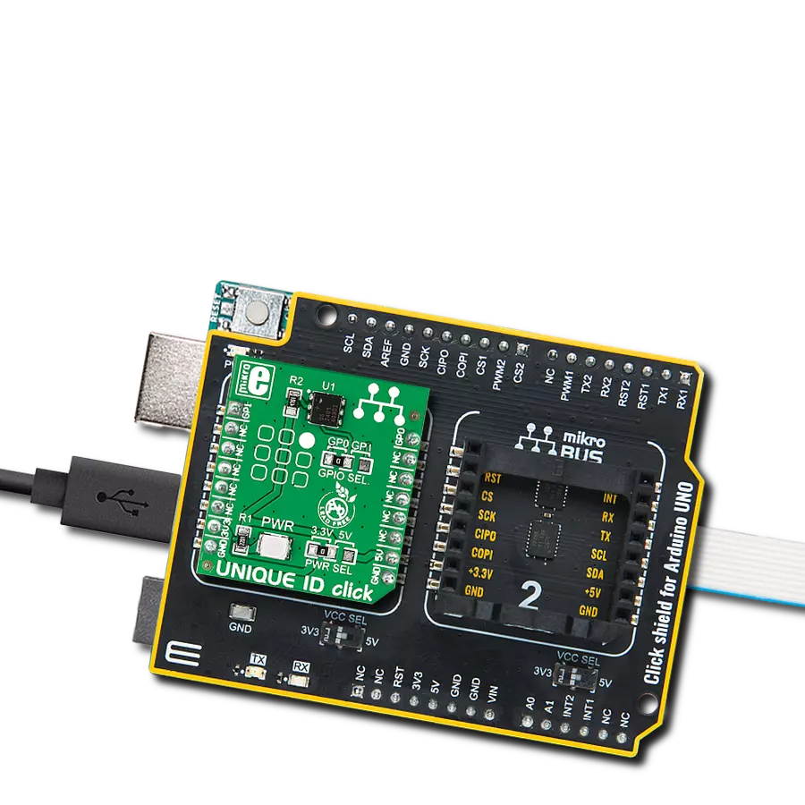
Unique ID Click is based on the DS2401, a guaranteed unique 64-bit ROM ID chip from Analog Devices. The 64-bit ROM includes a unique 48-bit serial number, an 8-bit CRC, and an 8-bit Family Code (01h). Its internal ROM is accessed via a single data line with a communication speed of up to 16.3Kbps. In perspective, multiple DS2401 devices can reside on a common 1-Wire net, with a built-in multidrop controller that ensures compatibility with other 1-Wire devices. The
DS2401 features presence pulse acknowledgment when the reader first applies a voltage, where the power for reading and writing the device is derived from the data line itself. The Unique ID Click uses a 1-Wire bus interface to communicate to the host MCU through one of the GPIOs (GP0, GP1) of the mikroBUS™ socket, selectable by the onboard GPIO SEL jumper. This protocol defines bus transactions regarding the bus state during specified time slots initiated on the falling edge of
sync pulses from the host bus. All data is read and written the least significant bit first. This Click board™ can operate with either 3.3V or 5V logic voltage levels selected via the PWR SEL jumper. This way, both 3.3V and 5V capable MCUs can use the communication lines properly. However, the Click board™ comes equipped with a library containing easy-to-use functions and an example code that can be used, as a reference, for further development.

Features overview
Development board
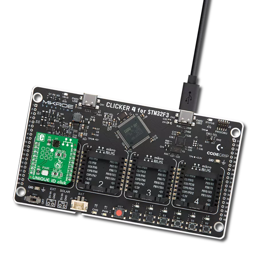
UNI Clicker is a compact development board designed as a complete solution that brings the flexibility of add-on Click boards™ to your favorite microcontroller, making it a perfect starter kit for implementing your ideas. It supports a wide range of microcontrollers, such as different ARM, PIC32, dsPIC, PIC, and AVR from various vendors like Microchip, ST, NXP, and TI (regardless of their number of pins), four mikroBUS™ sockets for Click board™ connectivity, a USB connector, LED indicators, buttons, a debugger/programmer connector, and two 26-pin headers for interfacing with external electronics. Thanks to innovative manufacturing technology, it allows you to build
gadgets with unique functionalities and features quickly. Each part of the UNI Clicker development kit contains the components necessary for the most efficient operation of the same board. In addition to the possibility of choosing the UNI Clicker programming method, using a third-party programmer or CODEGRIP/mikroProg connected to onboard JTAG/SWD header, the UNI Clicker board also includes a clean and regulated power supply module for the development kit. It provides two ways of board-powering; through the USB Type-C (USB-C) connector, where onboard voltage regulators provide the appropriate voltage levels to each component on the board, or using a Li-Po/Li
Ion battery via an onboard battery connector. All communication methods that mikroBUS™ itself supports are on this board (plus USB HOST/DEVICE), including the well-established mikroBUS™ socket, a standardized socket for the MCU card (SiBRAIN standard), and several user-configurable buttons and LED indicators. UNI Clicker is an integral part of the Mikroe ecosystem, allowing you to create a new application in minutes. Natively supported by Mikroe software tools, it covers many aspects of prototyping thanks to a considerable number of different Click boards™ (over a thousand boards), the number of which is growing every day.

Microcontroller Overview
MCU Card / MCU
Type
8th Generation
Architecture
ARM Cortex-M4
MCU Memory (KB)
1024
Silicon Vendor
STMicroelectronics
Pin count
64
RAM (Bytes)
327680
Used MCU Pins
mikroBUS™ mapper
Take a closer look
Click board™ Schematic

Step by step
Project assembly

Start by selecting your development board and Click board™. Begin with the UNI Clicker as your development board.


Track your results in real time
Application Output
1. Application Output - In Debug mode, the 'Application Output' window enables real-time data monitoring, offering direct insight into execution results. Ensure proper data display by configuring the environment correctly using the provided tutorial.

2. UART Terminal - Use the UART Terminal to monitor data transmission via a USB to UART converter, allowing direct communication between the Click board™ and your development system. Configure the baud rate and other serial settings according to your project's requirements to ensure proper functionality. For step-by-step setup instructions, refer to the provided tutorial.

3. Plot Output - The Plot feature offers a powerful way to visualize real-time sensor data, enabling trend analysis, debugging, and comparison of multiple data points. To set it up correctly, follow the provided tutorial, which includes a step-by-step example of using the Plot feature to display Click board™ readings. To use the Plot feature in your code, use the function: plot(*insert_graph_name*, variable_name);. This is a general format, and it is up to the user to replace 'insert_graph_name' with the actual graph name and 'variable_name' with the parameter to be displayed.

Software Support
Library Description
This library contains API for Unique ID Click driver.
Key functions:
uniqueid_read_id- This function reads Family Code and Serial Number of device's ROM memory
Open Source
Code example
The complete application code and a ready-to-use project are available through the NECTO Studio Package Manager for direct installation in the NECTO Studio. The application code can also be found on the MIKROE GitHub account.
/*!
 * @file main.c
 * @brief UNIQUE ID Click example.
 *
 * # Description
 * This example demonstrates the use of UNIQUE ID Click board by reading and
 * displaying Family Code and Serial Number on the UART Terminal.
 *
 * The demo application is composed of two sections :
 *
 * ## Application Init
 * Initializes both logger config object and
 * Click config object.
 *
 * ## Application Task
 * Demonstrates the usage of uniqueid_read_id function,
 * which stores the Family Code and Serial Number of the Click in
 * family_code and serial_num variables. Both values will be displayed
 * on the UART Terminal.
 *
 * @author Aleksandra Cvjeticanin
 *
 */

#include "board.h"
#include "log.h"
#include "uniqueid.h"

static uniqueid_t uniqueid;
static log_t logger;


void application_init ( void )
{
    log_cfg_t log_cfg;  /**< Logger config object. */
    uniqueid_cfg_t uniqueid_cfg;  /**< Click config object. */

    /**
     * Logger initialization.
     * Default baud rate: 115200
     * Default log level: LOG_LEVEL_DEBUG
     * @note If USB_UART_RX and USB_UART_TX
     * are defined as HAL_PIN_NC, you will
     * need to define them manually for log to work.
     * See @b LOG_MAP_USB_UART macro definition for detailed explanation.
     */
    LOG_MAP_USB_UART( log_cfg );
    log_init( &logger, &log_cfg );
    log_info( &logger, " Application Init " );

    // Click initialization
    uniqueid_cfg_setup( &uniqueid_cfg );
    UNIQUEID_MAP_MIKROBUS( uniqueid_cfg, MIKROBUS_1 );
    if ( ONE_WIRE_ERROR == uniqueid_init( &uniqueid, &uniqueid_cfg ) )
    {
        log_error( &logger, " Initialization error." );
        for ( ; ; );
    }

    log_info( &logger, " Application Task " );
}

void application_task ( void )
{
    uint8_t family_code;
    uint8_t serial_num[ 6 ];

    if ( UNIQUEID_OK == uniqueid_read_id( &uniqueid, &family_code, &serial_num[ 0 ] ) )
    {
        log_printf( &logger, "Family Code = 0x%.2X\r\n", ( uint16_t ) family_code );
        log_printf( &logger, "Serial Number = 0x%.2X%.2X%.2X%.2X%.2X%.2X\r\n",
                    ( uint16_t ) serial_num[ 0 ], ( uint16_t ) serial_num[ 1 ],
                    ( uint16_t ) serial_num[ 2 ], ( uint16_t ) serial_num[ 3 ],
                    ( uint16_t ) serial_num[ 4 ], ( uint16_t ) serial_num[ 5 ] );
    }

    Delay_ms ( 1000 );
}

int main ( void )
{
    /* Do not remove this line or clock might not be set correctly. */
    #ifdef PREINIT_SUPPORTED
    preinit();
    #endif

    application_init( );

    for ( ; ; )
    {
        application_task( );
    }

    return 0;
}

// ------------------------------------------------------------------------ END
Additional Support
Resources
Category:ID