Detect vibrations and accelerations with MC3419 and STM32F071VB for improved performance
Accelerate your world with 3D motion sensing!

Published Oct 02, 2023
Click board™
Accel 18 Click
Dev. board
UNI Clicker
Compiler
NECTO Studio
MCU
STM32F071VB
Our cutting-edge 3-axis accelerometer solution plays a crucial role in improving virtual reality experiences by tracking head movements and providing immersive, responsive environments
A
A
Hardware Overview
How does it work?
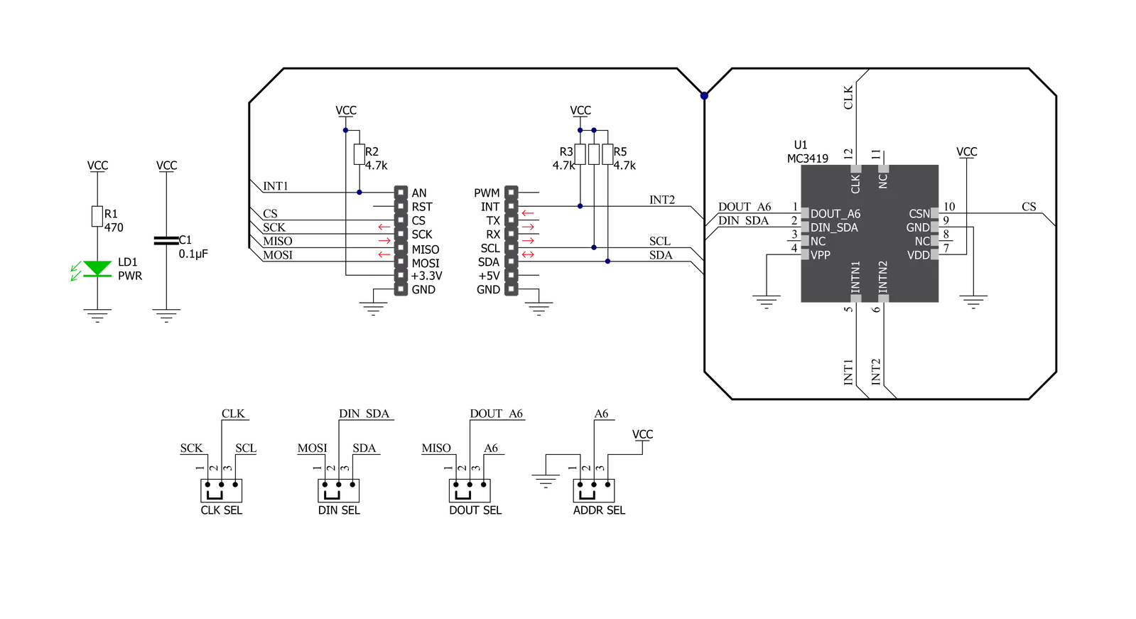
Accel 18 Click is based on the MC3419, a highly reliable 16-bit digital triaxial acceleration sensor with a feature set optimized for consumer product motion sensing from MEMSIC. The MC3419 is highly configurable with a programmable acceleration range of ±2/±4/±8/±16g and a dedicated motion block that implements the latest algorithms to detect any motion, shake, tilt/flip, and tilt 35 positions. It is optimized for high-performance applications by supporting full 16-bit resolution at Output Data Rates (ODR) up to 1KHz. In addition to all these features, it also has excellent temperature stability and low power consumption/low active current. The MC3419 has two operational states: STANDBY (following a Power-Up sequence) and WAKE state. Operative
states are software-controllable, with no automatic power control. In the WAKE state, acceleration data for the X, Y, and Z axes are sampled between 0.5 and 1000 samples/second. Changing from the STANDBY to WAKE state takes one sample period (less than 10 μs). Also, digital offset and gain calibration can be performed on the Accel board, if necessary, to reduce the effects of post-assembly influences and stresses, which may cause the sensor readings to be offset from their factory values. Accel 18 Click allows the use of both I2C and SPI interfaces with a maximum frequency of 1MHz for I2C and 10MHz for SPI communication. The selection can be made by positioning SMD jumpers labeled as COMM SEL in an appropriate position. Note that all the jumpers'
positions must be on the same side, or the Click board™ may become unresponsive. While the I2C interface is selected, the MC3419 allows choosing the least significant bit (LSB) of its I2C slave address using the SMD jumper labeled ADDR SEL. The Accel 18 also possesses two interrupts, I1 and I2, routed to the AN and INT pins on the mikroBUS™ used to signal MCU that an event has been sensed. This Click board™ can be operated only with a 3.3V logic voltage level. The board must perform appropriate logic voltage level conversion before using MCUs with different logic levels. Also, it comes equipped with a library containing functions and an example code that can be used as a reference for further development.


Features overview
Development board
UNI Clicker is a compact development board designed as a complete solution that brings the flexibility of add-on Click boards™ to your favorite microcontroller, making it a perfect starter kit for implementing your ideas. It supports a wide range of microcontrollers, such as different ARM, PIC32, dsPIC, PIC, and AVR from various vendors like Microchip, ST, NXP, and TI (regardless of their number of pins), four mikroBUS™ sockets for Click board™ connectivity, a USB connector, LED indicators, buttons, a debugger/programmer connector, and two 26-pin headers for interfacing with external electronics. Thanks to innovative manufacturing technology, it allows you to build
gadgets with unique functionalities and features quickly. Each part of the UNI Clicker development kit contains the components necessary for the most efficient operation of the same board. In addition to the possibility of choosing the UNI Clicker programming method, using a third-party programmer or CODEGRIP/mikroProg connected to onboard JTAG/SWD header, the UNI Clicker board also includes a clean and regulated power supply module for the development kit. It provides two ways of board-powering; through the USB Type-C (USB-C) connector, where onboard voltage regulators provide the appropriate voltage levels to each component on the board, or using a Li-Po/Li
Ion battery via an onboard battery connector. All communication methods that mikroBUS™ itself supports are on this board (plus USB HOST/DEVICE), including the well-established mikroBUS™ socket, a standardized socket for the MCU card (SiBRAIN standard), and several user-configurable buttons and LED indicators. UNI Clicker is an integral part of the Mikroe ecosystem, allowing you to create a new application in minutes. Natively supported by Mikroe software tools, it covers many aspects of prototyping thanks to a considerable number of different Click boards™ (over a thousand boards), the number of which is growing every day.

Microcontroller Overview
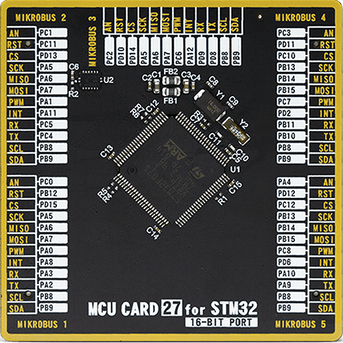
MCU Card / MCU
Type
8th Generation
Architecture
ARM Cortex-M0
MCU Memory (KB)
128
Silicon Vendor
STMicroelectronics
Pin count
100
RAM (Bytes)
16384
Used MCU Pins
mikroBUS™ mapper
Take a closer look
Click board™ Schematic
Step by step
Project assembly

Start by selecting your development board and Click board™. Begin with the UNI Clicker as your development board.


Software Support
Library Description
This library contains API for Accel 18 Click driver.
Key functions:
accel18_read_axes- Accel data readingaccel18_set_range- Set range configurationaccel18_get_interrupt_1- Get interrupt 1 pin state
Open Source
Code example
The complete application code and a ready-to-use project are available through the NECTO Studio Package Manager for direct installation in the NECTO Studio. The application code can also be found on the MIKROE GitHub account.
/*!
 * @file main.c
 * @brief Accel18 Click example
 *
 * # Description
 * This example application showcases ability of the device
 * to read axes values on detected interrupt.
 *
 * The demo application is composed of two sections :
 *
 * ## Application Init
 * Initialization of comunication modules(SPI/I2C, UART) and additional
 * two interrupt pins. Then configures device and sets 8g range and 10 Hz
 * data rate, with interrupt enabled.
 *
 * ## Application Task
 * Whenever interrupt is detected checks interrupt status for data ready,
 * and then reads x, y, and z axes, calculates value and logs result.
 *
 * @author Luka Filipovic
 *
 */

#include "board.h"
#include "log.h"
#include "accel18.h"

static accel18_t accel18;
static log_t logger;

void application_init ( void )
{
    log_cfg_t log_cfg;  /**< Logger config object. */
    accel18_cfg_t accel18_cfg;  /**< Click config object. */

    /**
     * Logger initialization.
     * Default baud rate: 115200
     * Default log level: LOG_LEVEL_DEBUG
     * @note If USB_UART_RX and USB_UART_TX
     * are defined as HAL_PIN_NC, you will
     * need to define them manually for log to work.
     * See @b LOG_MAP_USB_UART macro definition for detailed explanation.
     */
    LOG_MAP_USB_UART( log_cfg );
    log_init( &logger, &log_cfg );
    log_info( &logger, " Application Init " );

    // Click initialization.
    accel18_cfg_setup( &accel18_cfg );
    ACCEL18_MAP_MIKROBUS( accel18_cfg, MIKROBUS_1 );
    err_t init_flag  = accel18_init( &accel18, &accel18_cfg );
    if ( ( I2C_MASTER_ERROR == init_flag ) || ( SPI_MASTER_ERROR == init_flag ) )
    {
        log_error( &logger, " Application Init Error. " );
        log_info( &logger, " Please, run program again... " );

        for ( ; ; );
    }

    if ( accel18_default_cfg ( &accel18 ) )
    {
        log_error( &logger, " Default configuration. " );
        log_info( &logger, " Please, run program again... " );
        for ( ; ; );
    }

    log_info( &logger, " Application Task " );
}

void application_task ( void )
{
    accel18_axes_t axes_data;
    if ( !accel18_get_interrupt_1( &accel18 ) )
    {
        // Check interrupts
        uint8_t interrupt_state = 0;
        accel18_byte_read( &accel18, ACCEL18_REG_INTERRUPT_STATUS, &interrupt_state );
        if ( interrupt_state & ACCEL18_INT_ACQ_EN )
        {
            // Axis read
            accel18_read_axes( &accel18, &axes_data );
            log_printf( &logger, " > X[g]: %.2f\r\n", axes_data.x );
            log_printf( &logger, " > Y[g]: %.2f\r\n", axes_data.y );
            log_printf( &logger, " > Z[g]: %.2f\r\n", axes_data.z );
            log_printf( &logger, "**************************\r\n" );
        }
        // Clear interrupts
        if ( interrupt_state )
        {
            accel18_byte_write( &accel18, ACCEL18_REG_INTERRUPT_STATUS, ~interrupt_state );
        }
    }
}

int main ( void )
{
    /* Do not remove this line or clock might not be set correctly. */
    #ifdef PREINIT_SUPPORTED
    preinit();
    #endif

    application_init( );

    for ( ; ; )
    {
        application_task( );
    }

    return 0;
}

// ------------------------------------------------------------------------ END


