Elevate environmental wellness with SHT41A-AD1B, and STM32F407ZG - humidity, and air quality fusion
Clear skies, healthy lives

Published Aug 25, 2023
Click board™
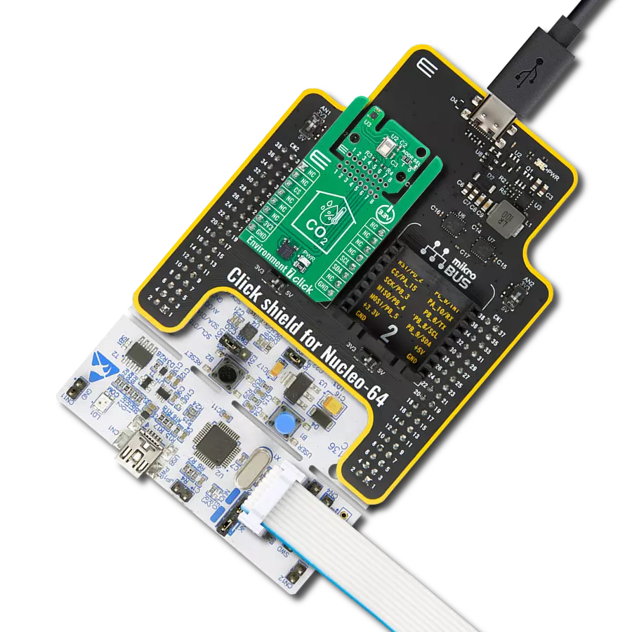
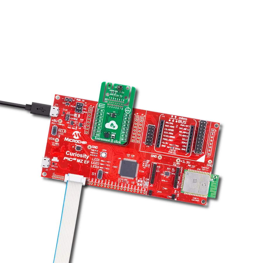
Environment 4 Click
Dev. board
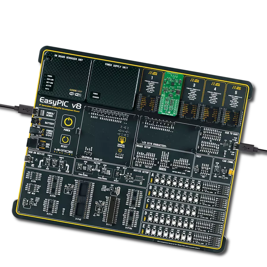
UNI Clicker
Compiler
NECTO Studio
MCU
STM32F407ZG
Monitor humidity levels and air quality indoors to ensure healthier living and working environments, reducing the risk of respiratory issues and allergies
A
A
Hardware Overview
How does it work?
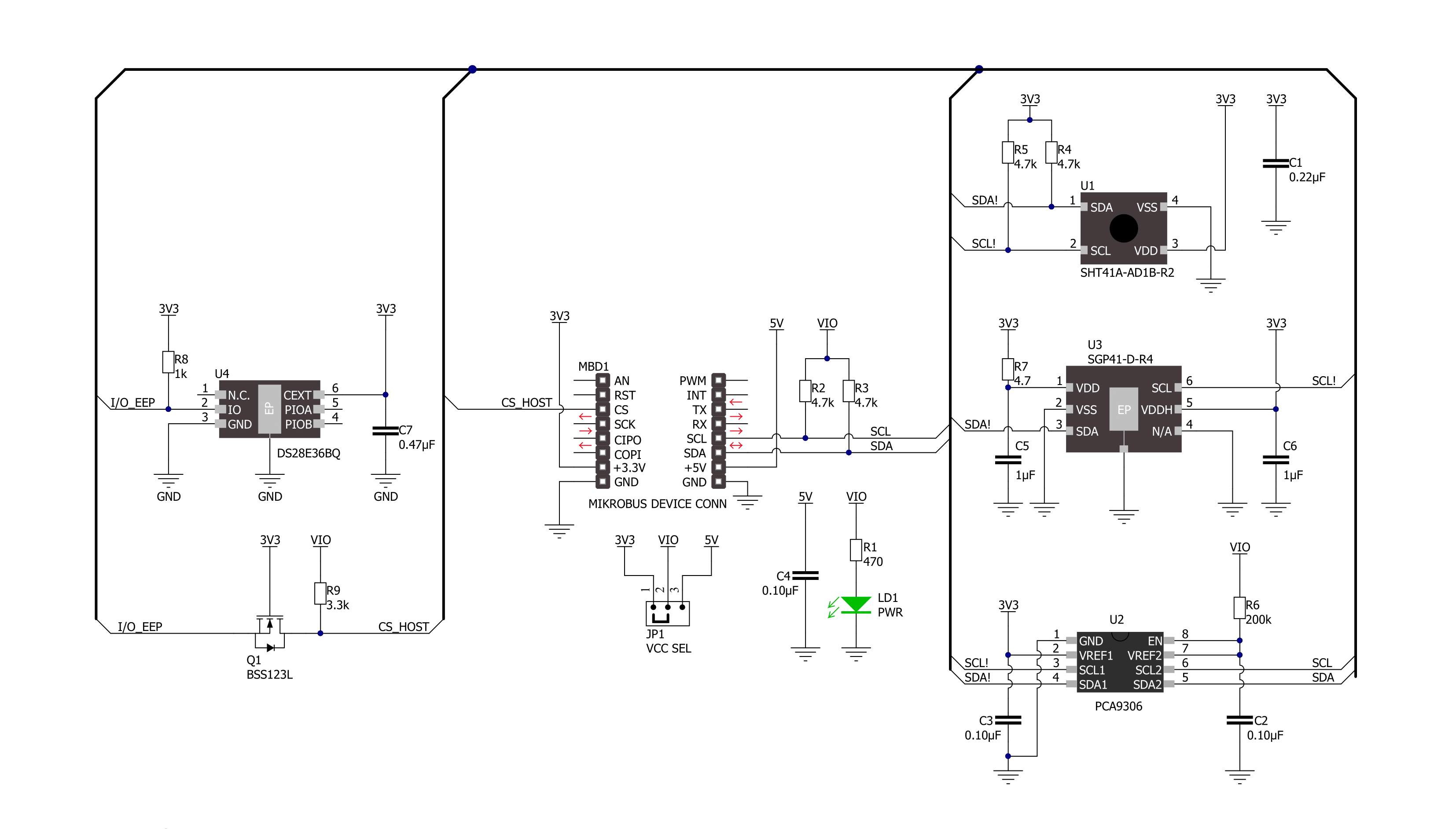
Environment 4 Click is based on the SHT41A-AD1B, a 4th-generation high-accuracy SHT relative humidity and temperature sensor, combined with the SGP41 MOx-based gas sensor from Sensirion. Based on Sensirion’s proven CMOSens® Technology and long-standing experience in humidity sensing, the SHT41A-AD1B ensures the highest precision. It covers extended operating humidity and temperature ranges from 0 to 100%RH and from -40°C to 125°C with accuracies of ±2%RH and ±0.3°C. The SHT41A-AD1B also specializes in automotive applications, fulfilling reliability requirements such as 85°C/85%RH accelerated life tests and AEC Q100 qualification. The SHT41A-AD1B performs best when operated within the recommended average temperature and humidity range of 5-60°C and 20-80%RH. Long-term exposure to conditions outside recommended normal range, especially at high
relative humidity, may temporarily offset the RH signal. After returning to the recommended average temperature and humidity range, the sensor will recover to within specifications. The complementary part of this combo solution is the SGP41, Sensirion’s new MOx-based gas sensor, that provides one VOC and one NOx-based indoor air quality signal. As mentioned, the SGP41 provides two raw digital signals sensitive to most VOCs typically found in indoor environments, plus oxidizing gases such as NOx or O3. This feature means that this board can constantly monitor the VOC and NOx situation, including potentially harmful events that humans cannot perceive. The raw signals are proportional to the logarithm of the resistance of the sensing material and are processed by Sensirion’s mighty Gas Index Algorithm. This can automatically trigger the removal of indoor air gas pollutants by air
treatment devices without requiring manual user intervention. Environment 4 Click communicates with MCU using the standard I2C 2-Wire interface. Since both sensors require only a 3.3V logic voltage level for operation, this Click board™ also features the PCA9306 voltage-level translator from Texas Instruments. The I2C interface bus lines are routed to the dual bidirectional voltage-level translator, allowing this Click board™ to work appropriately with 3.3V and 5V MCUs. This Click board™ can operate with either 3.3V or 5V logic voltage levels selected via the VCC SEL jumper. This way, both 3.3V and 5V capable MCUs can use the communication lines properly. Also, this Click board™ comes equipped with a library containing easy-to-use functions and an example code that can be used, as a reference, for further development.


Features overview
Development board
UNI Clicker is a compact development board designed as a complete solution that brings the flexibility of add-on Click boards™ to your favorite microcontroller, making it a perfect starter kit for implementing your ideas. It supports a wide range of microcontrollers, such as different ARM, PIC32, dsPIC, PIC, and AVR from various vendors like Microchip, ST, NXP, and TI (regardless of their number of pins), four mikroBUS™ sockets for Click board™ connectivity, a USB connector, LED indicators, buttons, a debugger/programmer connector, and two 26-pin headers for interfacing with external electronics. Thanks to innovative manufacturing technology, it allows you to build
gadgets with unique functionalities and features quickly. Each part of the UNI Clicker development kit contains the components necessary for the most efficient operation of the same board. In addition to the possibility of choosing the UNI Clicker programming method, using a third-party programmer or CODEGRIP/mikroProg connected to onboard JTAG/SWD header, the UNI Clicker board also includes a clean and regulated power supply module for the development kit. It provides two ways of board-powering; through the USB Type-C (USB-C) connector, where onboard voltage regulators provide the appropriate voltage levels to each component on the board, or using a Li-Po/Li
Ion battery via an onboard battery connector. All communication methods that mikroBUS™ itself supports are on this board (plus USB HOST/DEVICE), including the well-established mikroBUS™ socket, a standardized socket for the MCU card (SiBRAIN standard), and several user-configurable buttons and LED indicators. UNI Clicker is an integral part of the Mikroe ecosystem, allowing you to create a new application in minutes. Natively supported by Mikroe software tools, it covers many aspects of prototyping thanks to a considerable number of different Click boards™ (over a thousand boards), the number of which is growing every day.

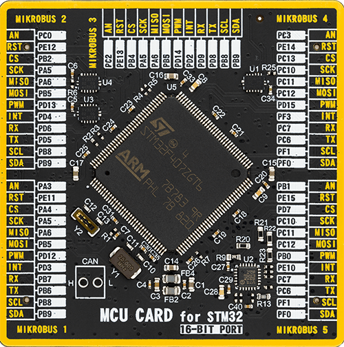
Microcontroller Overview
MCU Card / MCU
Type
8th Generation
Architecture
ARM Cortex-M4
MCU Memory (KB)
1024
Silicon Vendor
STMicroelectronics
Pin count
144
RAM (Bytes)
196608
Used MCU Pins
mikroBUS™ mapper
Take a closer look
Click board™ Schematic
Step by step
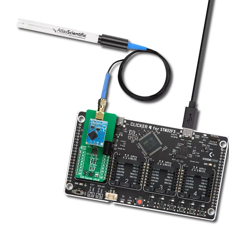
Project assembly

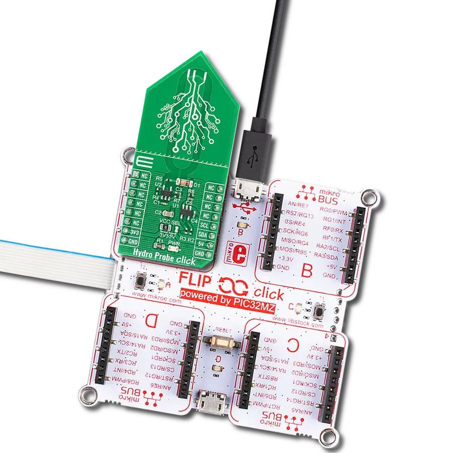
Start by selecting your development board and Click board™. Begin with the UNI Clicker as your development board.


Software Support
Library Description
This library contains API for Environment 4 Click driver.
Key functions:
environment4_sht_read_meas_hp- This function reads the temperature and humidity measurements with high precision from SHT41A deviceenvironment4_sgp_exe_conditioning- This function executes conditioning command for SGP41 device by using I2C serial interfaceenvironment4_sgp_meas_raw_signals- This function measures raw signals for SGP41 device by using I2C serial interface
Open Source
Code example
The complete application code and a ready-to-use project are available through the NECTO Studio Package Manager for direct installation in the NECTO Studio. The application code can also be found on the MIKROE GitHub account.
/*!
 * @file main.c
 * @brief Environment 4 Click example
 *
 * # Description
 * This example demonstrates the use of Environment 4 Click board by reading
 * the temperature and humidity data and calculating VOC and NOx indexes.
 *
 * The demo application is composed of two sections :
 *
 * ## Application Init
 * Initializes the driver, and reads and displays the SGP41 sensor unique serial number
 * and performs its build-in self-test. After that performs the SHT41 sensor software reset
 * and reads its unique serial number. Finally, it initializes the sensirion gas index algorithm
 * for VOC and NOx index calculation.
 *
 * ## Application Task
 * Reads the temperature (degC) and the relative humidity (%RH) data from SHT41 sensor with high precision.
 * For the first 10 seconds it executes NOx conditioning and after that it reads the raw signals for VOC and NOx
 * data and processes them with sensirion's gas index algorithm for calculating VOC and NOx indexes.
 * All data will be displayed on the USB UART approximately once per second.
 *
 * @note
 * Time required for reliably detecting VOC and NOx events on switching ON is typically less than 60 seconds.
 * Refer to the SGP41 sensor datasheet for more timing specifications.
 *
 * @author Stefan Filipovic
 *
 */

#include "board.h"
#include "log.h"
#include "environment4.h"
#include "sensirion_gas_index_algorithm.h"

static environment4_t environment4;
static log_t logger;

static GasIndexAlgorithmParams voc_params;
static GasIndexAlgorithmParams nox_params;

void application_init ( void )
{
    log_cfg_t log_cfg;  /**< Logger config object. */
    environment4_cfg_t environment4_cfg;  /**< Click config object. */

    /**
     * Logger initialization.
     * Default baud rate: 115200
     * Default log level: LOG_LEVEL_DEBUG
     * @note If USB_UART_RX and USB_UART_TX
     * are defined as HAL_PIN_NC, you will
     * need to define them manually for log to work.
     * See @b LOG_MAP_USB_UART macro definition for detailed explanation.
     */
    LOG_MAP_USB_UART( log_cfg );
    log_init( &logger, &log_cfg );
    log_info( &logger, " Application Init " );

    // Click initialization.
    environment4_cfg_setup( &environment4_cfg );
    ENVIRONMENT4_MAP_MIKROBUS( environment4_cfg, MIKROBUS_1 );
    if ( I2C_MASTER_ERROR == environment4_init( &environment4, &environment4_cfg ) )
    {
        log_error( &logger, " Communication init." );
        for ( ; ; );
    }

    uint16_t serial_num_sgp[ 3 ];
    if ( ENVIRONMENT4_OK == environment4_sgp_get_serial_num ( &environment4, serial_num_sgp ) )
    {
        log_printf ( &logger, " SGP Serial number: 0x%.4X%.4X%.4X\r\n",
                     serial_num_sgp[ 0 ], serial_num_sgp[ 1 ], serial_num_sgp[ 2 ] );
    }

    uint8_t test_result_sgp;
    if ( ENVIRONMENT4_OK == environment4_sgp_exe_self_test ( &environment4, &test_result_sgp ) )
    {
        log_printf ( &logger, " SGP Self test result: " );
        if ( ENVIRONMENT4_SGP_SELF_TEST_OK == test_result_sgp )
        {
            log_printf ( &logger, "OK\r\n" );
        }
        else
        {
            if ( ENVIRONMENT4_SGP_SELF_TEST_VOC_PIXEL == test_result_sgp )
            {
                log_printf ( &logger, "VOC pixel fail; " );
            }
            if ( ENVIRONMENT4_SGP_SELF_TEST_NOX_PIXEL == test_result_sgp )
            {
                log_printf ( &logger, "NOx pixel fail; " );
            }
            log_printf ( &logger, "\r\n" );
        }
    }

    if ( ENVIRONMENT4_OK == environment4_sht_soft_reset ( &environment4 ) )
    {
        log_printf ( &logger, " SHT Software reset\r\n" );
        Delay_1sec ( );
    }

    uint32_t serial_num_sht;
    if ( ENVIRONMENT4_OK == environment4_sht_read_serial_num ( &environment4, &serial_num_sht ) )
    {
        log_printf ( &logger, " SHT Serial number: 0x%.8LX\r\n", serial_num_sht );
    }

    log_printf ( &logger, " Initialize Gas Index algorithm for VOC and NOx\r\n" );
    GasIndexAlgorithm_init ( &voc_params, GasIndexAlgorithm_ALGORITHM_TYPE_VOC );
    GasIndexAlgorithm_init ( &nox_params, GasIndexAlgorithm_ALGORITHM_TYPE_NOX );

    log_info( &logger, " Application Task " );
}

void application_task ( void )
{
    float temperature, humidity;
    uint16_t comp_rh, comp_t, sraw_voc, sraw_nox;
    int32_t voc_index, nox_index;
    static uint8_t conditioning_num = 10;
    Delay_ms ( 1000 );
    if ( ENVIRONMENT4_OK == environment4_sht_read_meas_hp ( &environment4, &temperature, &humidity ) )
    {
        log_printf ( &logger, "\r\n Temperature: %.2f degC\r\n", temperature );
        log_printf ( &logger, " Humidity: %.2f %%RH\r\n", humidity );

        comp_rh = ( uint16_t ) ( humidity * ENVIRONMENT4_SHT_DATA_RESOLUTION /
                                 ( ENVIRONMENT4_SHT_ABS_MAX_HUM - ENVIRONMENT4_SHT_ABS_MIN_HUM ) );
        comp_t = ( uint16_t ) ( ( temperature - ENVIRONMENT4_SHT_ABS_MIN_TEMP ) * ENVIRONMENT4_SHT_DATA_RESOLUTION /
                                ( ENVIRONMENT4_SHT_ABS_MAX_TEMP - ENVIRONMENT4_SHT_ABS_MIN_TEMP ) );
        if ( conditioning_num )
        {
            if ( ENVIRONMENT4_OK == environment4_sgp_exe_conditioning ( &environment4, comp_rh, comp_t, &sraw_voc ) )
            {
                conditioning_num--;
            }
        }
        else
        {
            if ( ENVIRONMENT4_OK == environment4_sgp_meas_raw_signals ( &environment4, comp_rh, comp_t, &sraw_voc, &sraw_nox ) )
            {
                GasIndexAlgorithm_process( &voc_params, ( int32_t ) sraw_voc, &voc_index );
                GasIndexAlgorithm_process( &nox_params, ( int32_t ) sraw_nox, &nox_index );
                log_printf ( &logger, " VOC Index: %ld\r\n", voc_index );
                log_printf ( &logger, " NOx Index: %ld\r\n", nox_index );
            }
        }
    }
}

int main ( void )
{
    /* Do not remove this line or clock might not be set correctly. */
    #ifdef PREINIT_SUPPORTED
    preinit();
    #endif

    application_init( );

    for ( ; ; )
    {
        application_task( );
    }

    return 0;
}

// ------------------------------------------------------------------------ END
Additional Support
Resources
Category:Environmental