Support object stability control with KXTJ3-1057 and PIC18F46K20
Motion in focus: Where every move counts
Published Nov 01, 2023
Click board™
Accel 7 click
Dev. board
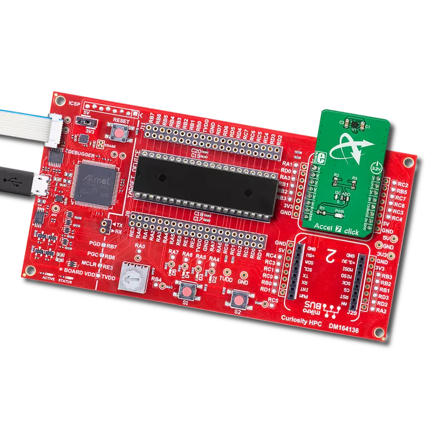
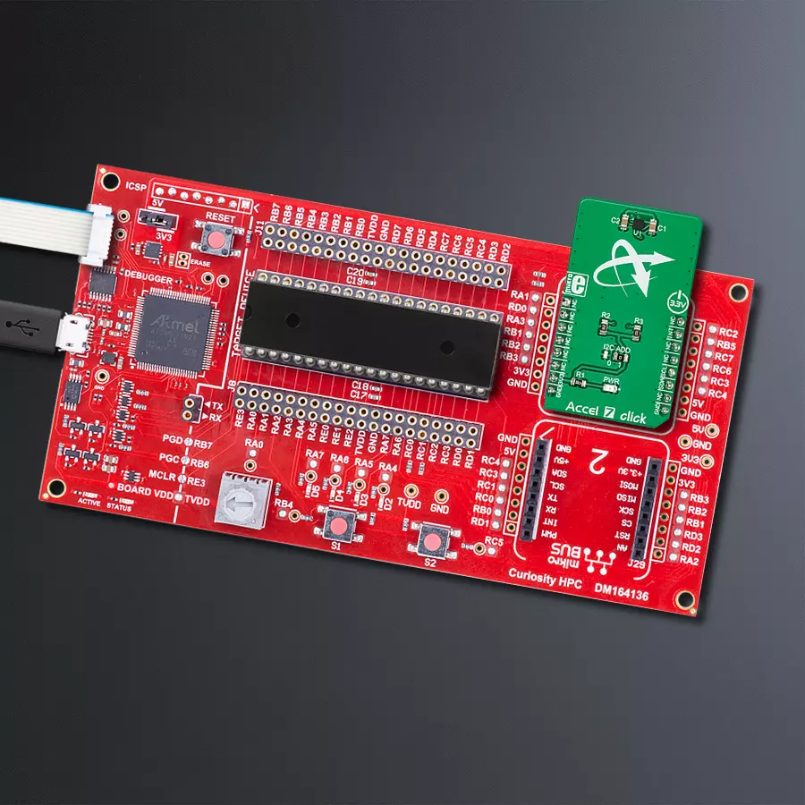
Curiosity HPC
Compiler
NECTO Studio
MCU
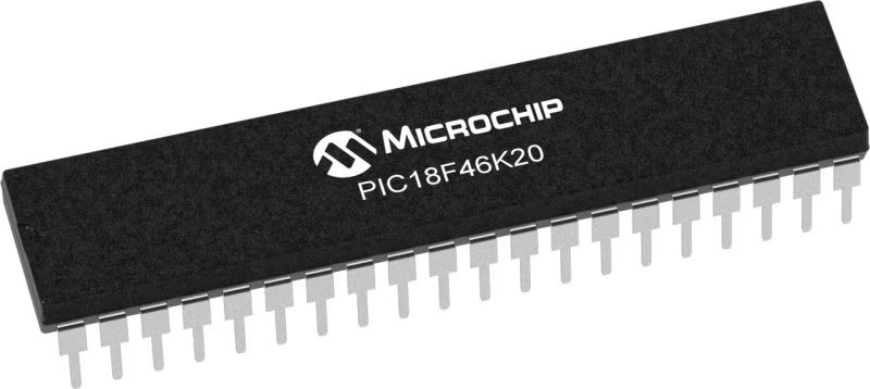
PIC18F46K20
This solution precisely measures and records changes in an object's velocity, making them invaluable in fields like robotics, automotive safety, and more
A
A
Hardware Overview
How does it work?
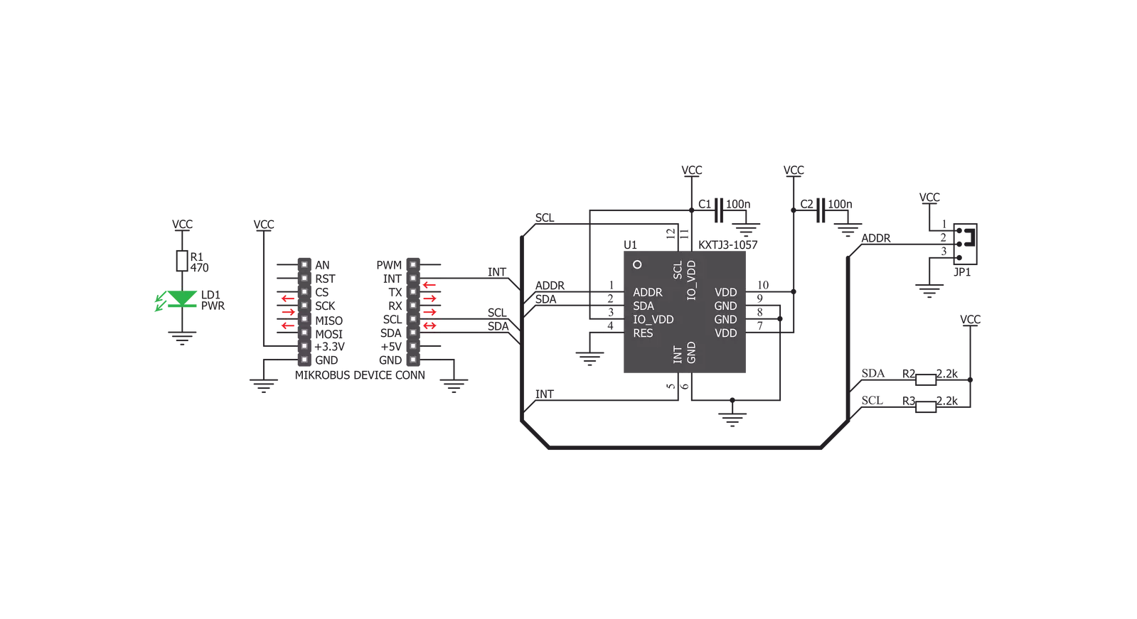
Accel 7 Click is based on the KXTJ3-1057, ±2g / ±4g / ±8g / ±16g tri-axis digital accelerometer from Rohm Semiconductor. This sensor utilizes an advanced acceleration sensing method, based on the differential capacitance. The integrated MEMS, produced with the proprietary Kionix technology, is composed of two plates. One is fixed to the substrate, while the other can move freely along a single axis. The acceleration causes the change in the capacitance between these plates, which is then processed by an integrated ASIC. The ASIC incorporates a capacitance-to-voltage amplifier which converts the differential capacitance of the MEMS sensor into an analog voltage, used as the input for the low-noise A/D converter (ADC). The integrated ASIC also contains the logic section used to set all the operational parameters of the KXTJ3-1057, such as the data rate, filter settings, interrupts, ADC resolution, and more. The ASIC also incorporates an OTP memory that contains the calibration parameters and other device-specific settings used on each power-on reset (POR) cycle. The ADC can be operated with the resolution of 8, 12, or 14 bits. This allows power consumption to be managed, as the lower resolution typically allows less power consumption. The power consumption is also affected by the output data rate value (ODR). The ODR value above 400Hz forces the high-resolution mode (14-bits) so the power consumption rises
exponentially as the ODR changes from 0.781Hz to 1600Hz. The ADC resolution, as well as the other operating parameters of the KXTJ3-1057 IC can be adjusted by using two configuration registers. Some options can only be altered while the IC operates in the Stand-by mode. The acceleration range can be selected from ±2g to ±16g. The choice of the ADC resolution is directly related with the number of counts for a certain acceleration range. For example, using ±2g range with the 8-bit ADC resolution means that the whole range between -2g and +2g will be covered by 255 values, from -127 to +127. Therefore, the output of 127 will be equivalent of 2g acceleration (more precisely, 1.984g). The datasheet of the KXTJ3-1057 offers a comprehensive set of tables with these settings. However, the Accel 7 click comes with the library that contains simple to use functions which simplify the acceleration measurements. The interrupt engine allows interrupt reporting on a dedicated INT pin. There are multiple interrupt status registers, allowing both combined and individual events to be read. This allows the INT pin to be used more flexible. Depending on the settings, it is possible to pulse and latch this pin. When latched, it will stay asserted until the specific register is read (INT_REL in the datasheet). Pulsed operation will produce a short pulse on this pin, but the status bits will remain set, until the INT_REL register is read.
Un-latched mode allows the status bits to be cleared automatically, so there is no need to read the INT_REL register. One distinctive feature of the KXTJ3-1057 is that it can generate a Wake-up (motion detection) interrupt, when the acceleration measurement exceeds the value stored in the Wake-up threshold registers. In this case, a bit in the interrupt status register will indicate that a Wake-up event occurred. The Wake-up interrupt features a debouncing counter: if an acceleration value has exceeded the threshold and remained above this threshold during a programmed number of counts, an interrupt event will be reported. To distinguish between two successive movement events, there is yet another countdown timer, which sets the non-activity time interval before another Wake-up event can be reported. Note that the thresholds use fixed g-range and resolution, regardless of user settings. Each KXTJ3-1057 device is factory calibrated, and its calibration parameters are stored in the one-time programmable memory (OTP). These parameters include the gain corrections and offset calibration. After each POR cycle, these calibration values are automatically applied, reducing the output error. Along with the used MEMS differential sensing technology, this reduces the measurement error to a virtually unmeasurable value. A built-in self-test function allows reliable operation of the Accel 7 click.


Features overview
Development board
Curiosity HPC, standing for Curiosity High Pin Count (HPC) development board, supports 28- and 40-pin 8-bit PIC MCUs specially designed by Microchip for the needs of rapid development of embedded applications. This board has two unique PDIP sockets, surrounded by dual-row expansion headers, allowing connectivity to all pins on the populated PIC MCUs. It also contains a powerful onboard PICkit™ (PKOB), eliminating the need for an external programming/debugging tool, two mikroBUS™ sockets for Click board™ connectivity, a USB connector, a set of indicator LEDs, push button switches and a variable potentiometer. All
these features allow you to combine the strength of Microchip and Mikroe and create custom electronic solutions more efficiently than ever. Each part of the Curiosity HPC development board contains the components necessary for the most efficient operation of the same board. An integrated onboard PICkit™ (PKOB) allows low-voltage programming and in-circuit debugging for all supported devices. When used with the MPLAB® X Integrated Development Environment (IDE, version 3.0 or higher) or MPLAB® Xpress IDE, in-circuit debugging allows users to run, modify, and troubleshoot their custom software and hardware
quickly without the need for additional debugging tools. Besides, it includes a clean and regulated power supply block for the development board via the USB Micro-B connector, alongside all communication methods that mikroBUS™ itself supports. Curiosity HPC development board allows you to create a new application in just a few steps. Natively supported by Microchip software tools, it covers many aspects of prototyping thanks to many number of different Click boards™ (over a thousand boards), the number of which is growing daily.

Microcontroller Overview
MCU Card / MCU
Architecture
PIC
MCU Memory (KB)
64
Silicon Vendor
Microchip
Pin count
40
RAM (Bytes)
3936
Used MCU Pins
mikroBUS™ mapper
Take a closer look
Click board™ Schematic
Step by step
Project assembly

Start by selecting your development board and Click board™. Begin with the Curiosity HPC as your development board.


Track your results in real time
Application Output
1. Application Output - In Debug mode, the 'Application Output' window enables real-time data monitoring, offering direct insight into execution results. Ensure proper data display by configuring the environment correctly using the provided tutorial.

2. UART Terminal - Use the UART Terminal to monitor data transmission via a USB to UART converter, allowing direct communication between the Click board™ and your development system. Configure the baud rate and other serial settings according to your project's requirements to ensure proper functionality. For step-by-step setup instructions, refer to the provided tutorial.

3. Plot Output - The Plot feature offers a powerful way to visualize real-time sensor data, enabling trend analysis, debugging, and comparison of multiple data points. To set it up correctly, follow the provided tutorial, which includes a step-by-step example of using the Plot feature to display Click board™ readings. To use the Plot feature in your code, use the function: plot(*insert_graph_name*, variable_name);. This is a general format, and it is up to the user to replace 'insert_graph_name' with the actual graph name and 'variable_name' with the parameter to be displayed.

Software Support
Library Description
This library contains API for Accel 7 Click driver.
Key functions:
accel7_get_axis- This function reads two bytes of data from the desired axis registeraccel7_res_range_cfg- This function calculates the resolution and range values which are used in the default_cfg() functionaccel7_get_interrupt_state- This function reads the state of the interrupt pin
Open Source
Code example
The complete application code and a ready-to-use project are available through the NECTO Studio Package Manager for direct installation in the NECTO Studio. The application code can also be found on the MIKROE GitHub account.
/*!
 * \file
 * \brief Accel7 Click example
 *
 * # Description
 * This example shows how data from all three axes is collected, processed and later
 * displayed in the logger module.
 *
 * The demo application is composed of two sections :
 *
 * ## Application Init
 * This is where the logger and the Click modules get initialised and configured.
 *
 * ## Application Task
 * This is where the data gets collected, processed and printed out.
 *
 * \author MikroE Team
 *
 */
// ------------------------------------------------------------------- INCLUDES

#include "board.h"
#include "log.h"
#include "accel7.h"

// ------------------------------------------------------------------ VARIABLES

static accel7_t accel7;
static log_t logger;

// ------------------------------------------------------ APPLICATION FUNCTIONS

void application_init (  )
{
    log_cfg_t log_cfg;
    accel7_cfg_t cfg;

    uint8_t resolution = ACCEL7_DATA_RESP_14bit;
    uint8_t range = ACCEL7_RANGE_8g;

    /**
     * Logger initialization.
     * Default baud rate: 115200
     * Default log level: LOG_LEVEL_DEBUG
     * @note If USB_UART_RX and USB_UART_TX
     * are defined as HAL_PIN_NC, you will
     * need to define them manually for log to work.
     * See @b LOG_MAP_USB_UART macro definition for detailed explanation.
     */
    LOG_MAP_USB_UART( log_cfg );
    log_init( &logger, &log_cfg );
    log_info( &logger, "---- Application Init ----" );

    //  Click initialization.

    accel7_cfg_setup( &cfg );
    ACCEL7_MAP_MIKROBUS( cfg, MIKROBUS_1 );
    accel7_init( &accel7, &cfg );
    accel7_default_cfg( &accel7, resolution, range );

    Delay_ms ( 100 );
}

void application_task (  )
{
    int16_t x_axis;
    int16_t y_axis;
    int16_t z_axis;

    x_axis = accel7_get_axis( &accel7, ACCEL7_AXIS_X );
    y_axis = accel7_get_axis( &accel7, ACCEL7_AXIS_Y );
    z_axis = accel7_get_axis( &accel7, ACCEL7_AXIS_Z );

    log_printf( &logger, "X axis: %d\r\n", x_axis );
    log_printf( &logger, "Y axis: %d\r\n", y_axis );
    log_printf( &logger, "Z axis: %d\r\n", z_axis );

    log_printf( &logger, "------------------\r\n" );

    Delay_ms ( 1000 );
}

int main ( void )
{
    /* Do not remove this line or clock might not be set correctly. */
    #ifdef PREINIT_SUPPORTED
    preinit();
    #endif

    application_init( );

    for ( ; ; )
    {
        application_task( );
    }

    return 0;
}

// ------------------------------------------------------------------------ END
Additional Support
Resources
Category:Motion


