Make your environments smarter, safer, and more responsive with VCNL4040 and PIC18F4680
Proximity detection solution: Beyond the horizon

Published Nov 01, 2023
Click board™
Proximity 9 Click
Dev Board
Curiosity HPC
Compiler
NECTO Studio
MCU
PIC18F4680
Let us unveil the invisible connections that proximity detection brings to light, enhancing your everyday experiences
A
A
Hardware Overview
How does it work?
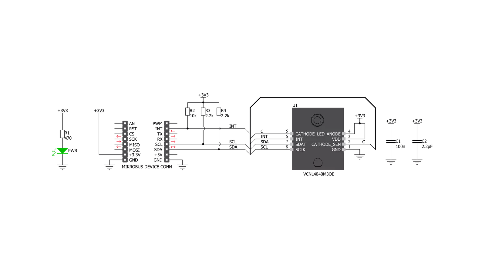
Proximity 9 Click is based on the VCNL4040, a fully integrated proximity and ambient light sensor with I2C interface from Vishay. It is an advanced 16bit Ambient Light Sensor (ALS) which makes use of the proprietary Filtron™ technology, providing spectral response near to a human eye. The ALS sensor also helps with the flickering of fluorescent light sources, and background light cancellation, reducing the workload of the host MCU. This sensor features a 940 nm IRED on-chip, driven by a programmable current sink driver. The VCNL4040 is also thermally compensated, allowing very accurate readings within the range between -40⁰C and +85⁰C. The Proximity Sensing (PS) section of the VCNL4040 IC implements several solutions for the improved proximity detection of objects of any color. It relies on the detection of the reflected IR light from the IRED emitter. Features such as the immunity to a red glow, intelligent crosstalk phenomenon reduction,
smart persistence scheme for false interrupt triggering prevention, programmable IRED current, selectable sampling resolution, and selectable integration time, help achieving a reliable and accurate proximity detection. The processed readings of the ALS and PS sensors can be fetched from the respective registers via the I2C interface. The I2C bus lines are routed to the respective mikroBUS™ I2C pins: SCL is the I2C clock and SDA is the I2C data line. Proximity 9 click offers programmable interrupt engine. The INT pin is routed to the mikroBUS™ INT pin and it is pulled up by the onboard resistor. When asserted, it is driven to a LOW logic level. The interrupt can be programmed to be triggered whenever PS threshold window is exceeded, for a programmed number of times (interrupt persistence). There are two interrupt modes: the interrupt will remain latched in the normal mode until the interrupt status flag is read by the host firmware. If set to a
logic mode, the interrupt will be asserted when the PS value rises above the high threshold level, and de-asserted when the PS value falls below the low threshold level. The logic mode is useful when an autonomous operation with some external circuit is required, while the normal mode is best suited to be used with the MCU. The INT pin is routed to the INT pin of the mikroBUS™. The Click board™ is supported by the mikroSDK library, which contains functions for simplified development. The mikroSDK functions are well-documented, but there is still a need, the datasheet of the VCNL4040 offers a listing of all the registers and their specific functions. The Click board™ is designed to work with 3.3V only. When using it with MCUs that use 5V levels for their communication, a proper level translation circuit should be used.


Features overview
Development board
Curiosity HPC, standing for Curiosity High Pin Count (HPC) development board, supports 28- and 40-pin 8-bit PIC MCUs specially designed by Microchip for the needs of rapid development of embedded applications. This board has two unique PDIP sockets, surrounded by dual-row expansion headers, allowing connectivity to all pins on the populated PIC MCUs. It also contains a powerful onboard PICkit™ (PKOB), eliminating the need for an external programming/debugging tool, two mikroBUS™ sockets for Click board™ connectivity, a USB connector, a set of indicator LEDs, push button switches and a variable potentiometer. All
these features allow you to combine the strength of Microchip and Mikroe and create custom electronic solutions more efficiently than ever. Each part of the Curiosity HPC development board contains the components necessary for the most efficient operation of the same board. An integrated onboard PICkit™ (PKOB) allows low-voltage programming and in-circuit debugging for all supported devices. When used with the MPLAB® X Integrated Development Environment (IDE, version 3.0 or higher) or MPLAB® Xpress IDE, in-circuit debugging allows users to run, modify, and troubleshoot their custom software and hardware
quickly without the need for additional debugging tools. Besides, it includes a clean and regulated power supply block for the development board via the USB Micro-B connector, alongside all communication methods that mikroBUS™ itself supports. Curiosity HPC development board allows you to create a new application in just a few steps. Natively supported by Microchip software tools, it covers many aspects of prototyping thanks to many number of different Click boards™ (over a thousand boards), the number of which is growing daily.

Microcontroller Overview
MCU Card / MCU
Architecture
PIC
MCU Memory (KB)
64
Silicon Vendor
Microchip
Pin count
40
RAM (Bytes)
3328
Used MCU Pins
mikroBUS™ mapper
Take a closer look
Schematic
Step by step
Project assembly

Start by selecting your development board and Click board™. Begin with the Curiosity HPC as your development board.


Track your results in real time
Application Output
After loading the code example, pressing the "DEBUG" button builds and programs it on the selected setup.

After programming is completed, a header with buttons for various actions available in the IDE appears. By clicking the green "PLAY "button, we start reading the results achieved with Click board™.

Upon completion of programming, the Application Output tab is automatically opened, where the achieved result can be read. In case of an inability to perform the Debug function, check if a proper connection between the MCU used by the setup and the CODEGRIP programmer has been established. A detailed explanation of the CODEGRIP-board connection can be found in the CODEGRIP User Manual. Please find it in the RESOURCES section.

Software Support
Library Description
This library contains API for Proximity 9 Click driver.
Key functions:
proximity9_check_int_pin- INT Pin Check functionproximity9_check_int_flag- INT Flag Check functionproximity9_get_als_lux- ALS Get function
Open Source
Code example
This example can be found in NECTO Studio. Feel free to download the code, or you can copy the code below.
/*!
 * \file
 * \brief Proximity9 Click example
 *
 * # Description
 * This application is proximity sensing (PS) and ambient light sensing (ALS) device.
 *
 * The demo application is composed of two sections :
 *
 * ## Application Init
 * Initializes I2C interface and performs a device configurations.
 *
 * ## Application Task
 * Performs a data reading and interrupt flag checking.
 * Allows data and interrupt flags messages to be showed on the uart terminal.
 *
 * *note:*
 * The ALS sensitivity depends on the ALS integration time setting.
 * The longer integration time has higher sensitivity.
 * The Proximity (PS) output data can be set to 12-bit or 16-bit resolution.
 *
 * \author MikroE Team
 *
 */
// ------------------------------------------------------------------- INCLUDES

#include "board.h"
#include "log.h"
#include "proximity9.h"

// ------------------------------------------------------------------ VARIABLES

static proximity9_t proximity9;
static log_t logger;

// ------------------------------------------------------ APPLICATION FUNCTIONS

void application_init ( void )
{
    log_cfg_t log_cfg;
    proximity9_cfg_t cfg;

    /**
     * Logger initialization.
     * Default baud rate: 115200
     * Default log level: LOG_LEVEL_DEBUG
     * @note If USB_UART_RX and USB_UART_TX
     * are defined as HAL_PIN_NC, you will
     * need to define them manually for log to work.
     * See @b LOG_MAP_USB_UART macro definition for detailed explanation.
     */
    LOG_MAP_USB_UART( log_cfg );
    log_init( &logger, &log_cfg );
    log_info( &logger, "---- Application Init ----" );

    //  Click initialization.

    proximity9_cfg_setup( &cfg );
    PROXIMITY9_MAP_MIKROBUS( cfg, MIKROBUS_1 );
    proximity9_init( &proximity9, &cfg );

    proximity9_default_cfg( &proximity9 );

    log_printf( &logger, "** Proximity 9 is initialized ** \r\n" );
    log_printf( &logger, "************************************ \r\n" );
    Delay_ms( 300 );
}

void application_task ( )
{
    uint8_t int_check;
    uint16_t prox_data;
    float als_data;
    uint8_t temp;

    als_data = proximity9_get_als_lux( &proximity9 );
    proximity9_read_register( &proximity9, PROXIMITY9_PS_DATA_REG, &prox_data );
    temp = PROXIMITY9_PS_IF_CLOSE_FLAG | PROXIMITY9_PS_IF_AWAY_FLAG;
    int_check = proximity9_check_int_flag( &proximity9, temp );

    log_printf( &logger, "** ALS: %.2f lux \r\n", als_data );
    log_printf( &logger, "** PROXIMITY: %d \r\n", prox_data );

    if ( int_check == PROXIMITY9_PS_IF_CLOSE_FLAG )
    {
        log_printf( &logger, "** Object is close! \r\n" );
        log_printf( &logger, "************************************ \r\n" );
        Delay_ms( 1000 );
    }
    if ( int_check == PROXIMITY9_PS_IF_AWAY_FLAG )
    {
        log_printf( &logger, "** Object is away!\r\n" );
        log_printf( &logger, "************************************ \r\n" );
        Delay_ms( 1000 );
    }
    if ( int_check == PROXIMITY9_INT_CLEARED )
    {
        log_printf( &logger, "************************************ \r\n" );
        Delay_ms( 1000 );
    }
}

void main ( void )
{
    application_init( );

    for ( ; ; )
    {
        application_task( );
    }
}


// ------------------------------------------------------------------------ END


