Efficiently switch electrical loads with G5V-1 and PIC32MZ2048EFH100 without any noise
Switch smarter, not harder: Discover our SPDT relay solution

Published Oct 18, 2023
Click board™
Signal Relay Click
Dev. board
Flip&Click PIC32MZ
Compiler
NECTO Studio
MCU
PIC32MZ2048EFH100
Upgrade your systems with silent, spark-free switching by implementing our SPDT relay solution
A
A
Hardware Overview
How does it work?
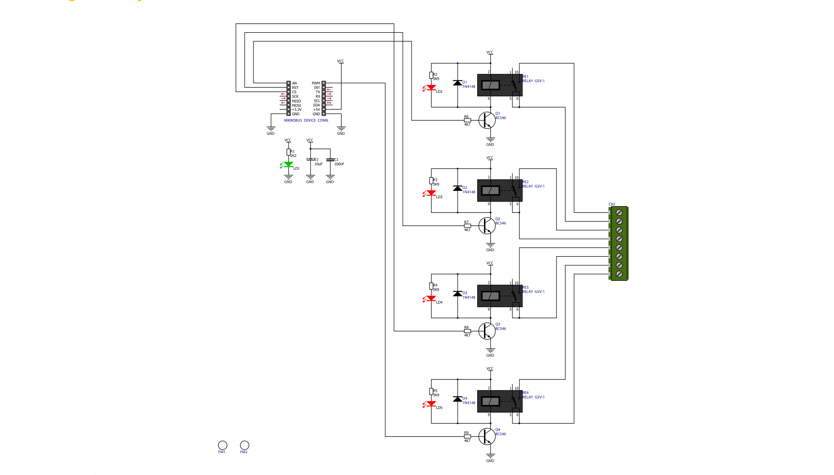
Signal Relay Click is based on four G5V-1s, an ultra-miniature, highly sensitive single-pole double-throw (SPDT) relays for signal circuits from Omron. The G5V-1 relays feature wide switching power of up to 1A, high sensitivity with 150mW of nominal coil power consumption, and fully-sealed construction, thus offering environmental resistance. The relay internal single-type contact is made as a single crossbar of gold and silver alloy. The relay output markings of the screw terminal
are labeled at the bottom of this Click board™ with additional info. Every relay has its LED for visual presentation, labeled OUT1-4. The Signal Relay Click uses four mikroBUS™ pins labeled RE1, RE2, RE3, and RE4 to communicate with the host microcontroller. All relays are driven through small amplifier transistors as a safe solution for the relays’ current and their impact on the host MCU. The Signal Relay Click also features small signal fast switching diodes on each relay to prevent
electrical noise. One thing to note is that the relays’ coils are 5-volts driven. This Click board™ can be operated only with a 5V logic voltage level. The board must perform appropriate logic voltage level conversion before using MCUs with different logic levels. Also, it comes equipped with a library containing functions and an example code that can be used as a reference for further development.

Features overview
Development board
Flip&Click PIC32MZ is a compact development board designed as a complete solution that brings the flexibility of add-on Click boards™ to your favorite microcontroller, making it a perfect starter kit for implementing your ideas. It comes with an onboard 32-bit PIC32MZ microcontroller, the PIC32MZ2048EFH100 from Microchip, four mikroBUS™ sockets for Click board™ connectivity, two USB connectors, LED indicators, buttons, debugger/programmer connectors, and two headers compatible with Arduino-UNO pinout. Thanks to innovative manufacturing technology,
it allows you to build gadgets with unique functionalities and features quickly. Each part of the Flip&Click PIC32MZ development kit contains the components necessary for the most efficient operation of the same board. In addition, there is the possibility of choosing the Flip&Click PIC32MZ programming method, using the chipKIT bootloader (Arduino-style development environment) or our USB HID bootloader using mikroC, mikroBasic, and mikroPascal for PIC32. This kit includes a clean and regulated power supply block through the USB Type-C (USB-C) connector. All communication
methods that mikroBUS™ itself supports are on this board, including the well-established mikroBUS™ socket, user-configurable buttons, and LED indicators. Flip&Click PIC32MZ development kit allows you to create a new application in minutes. Natively supported by Mikroe software tools, it covers many aspects of prototyping thanks to a considerable number of different Click boards™ (over a thousand boards), the number of which is growing every day.

Microcontroller Overview
MCU Card / MCU

Architecture
PIC32
MCU Memory (KB)
2048
Silicon Vendor
Microchip
Pin count
100
RAM (Bytes)
524288
Used MCU Pins
mikroBUS™ mapper
Take a closer look
Click board™ Schematic
Step by step
Project assembly

Start by selecting your development board and Click board™. Begin with the Flip&Click PIC32MZ as your development board.


Track your results in real time
Application Output
1. Application Output - In Debug mode, the 'Application Output' window enables real-time data monitoring, offering direct insight into execution results. Ensure proper data display by configuring the environment correctly using the provided tutorial.

2. UART Terminal - Use the UART Terminal to monitor data transmission via a USB to UART converter, allowing direct communication between the Click board™ and your development system. Configure the baud rate and other serial settings according to your project's requirements to ensure proper functionality. For step-by-step setup instructions, refer to the provided tutorial.

3. Plot Output - The Plot feature offers a powerful way to visualize real-time sensor data, enabling trend analysis, debugging, and comparison of multiple data points. To set it up correctly, follow the provided tutorial, which includes a step-by-step example of using the Plot feature to display Click board™ readings. To use the Plot feature in your code, use the function: plot(*insert_graph_name*, variable_name);. This is a general format, and it is up to the user to replace 'insert_graph_name' with the actual graph name and 'variable_name' with the parameter to be displayed.

Software Support
Library Description
This library contains API for Signal Relay Click driver.
Key functions:
signalrelay_relay_state- Relays state
Open Source
Code example
The complete application code and a ready-to-use project are available through the NECTO Studio Package Manager for direct installation in the NECTO Studio. The application code can also be found on the MIKROE GitHub account.
/*!
 * \file
 * \brief Signal Realy Click example
 *
 * # Description
 * Demo application is used to shows basic controls Signal Relay Click.
 *
 * The demo application is composed of two sections :
 *
 * ## Application Init
 * Configuring Clicks and log objects.
 * Settings the Click in the default configuration.
 *
 * ## Application Task
 * Alternately sets relays to ON-OFF state...
 *
 * \author Katarina Perendic
 *
 */
// ------------------------------------------------------------------- INCLUDES

#include "board.h"
#include "log.h"
#include "signalrelay.h"

// ------------------------------------------------------------------ VARIABLES

static signalrelay_t signalrelay;
static log_t logger;

// ------------------------------------------------------ APPLICATION FUNCTIONS

void application_init ( void )
{
    log_cfg_t log_cfg;
    signalrelay_cfg_t cfg;

    /**
     * Logger initialization.
     * Default baud rate: 115200
     * Default log level: LOG_LEVEL_DEBUG
     * @note If USB_UART_RX and USB_UART_TX
     * are defined as HAL_PIN_NC, you will
     * need to define them manually for log to work.
     * See @b LOG_MAP_USB_UART macro definition for detailed explanation.
     */
    LOG_MAP_USB_UART( log_cfg );
    log_init( &logger, &log_cfg );
    log_info( &logger, "---- Application Init ----");

    //  Click initialization.

    signalrelay_cfg_setup( &cfg );
    SIGNALRELAY_MAP_MIKROBUS( cfg, MIKROBUS_1 );
    signalrelay_init( &signalrelay, &cfg );

    signalrelay_default_cfg ( &signalrelay );
}

void application_task ( void )
{
    uint8_t cnt;

    //  Task implementation.

    for ( cnt = 1; cnt <= 4; cnt++ )
    {
        log_info( &logger, " *** Relay [ %d ] ON ", cnt );
        signalrelay_relay_state( &signalrelay, cnt, SIGNALRELAY_STATE_ON );
        Delay_ms ( 200 );
        log_info( &logger, " *** Relay [ %d ] OFF ", cnt );
        signalrelay_relay_state( &signalrelay, cnt, SIGNALRELAY_STATE_OFF );
        Delay_ms ( 200 );
    }
}

int main ( void )
{
    /* Do not remove this line or clock might not be set correctly. */
    #ifdef PREINIT_SUPPORTED
    preinit();
    #endif

    application_init( );

    for ( ; ; )
    {
        application_task( );
    }

    return 0;
}


// ------------------------------------------------------------------------ END


