Maximize performance with this buck-boost solution based on the ISL85403 and PIC32MZ2048EFH100
Tailor power to your needs with ease

Published Aug 03, 2023
Click board™
Buck-Boost 3 Click
Dev. board
Flip&Click PIC32MZ
Compiler
NECTO Studio
MCU
PIC32MZ2048EFH100
Thanks to our advanced Buck-Boost combo, achieve broad input voltage range regulation with seamless transition between step-up and step-down modes
A
A
Hardware Overview
How does it work?
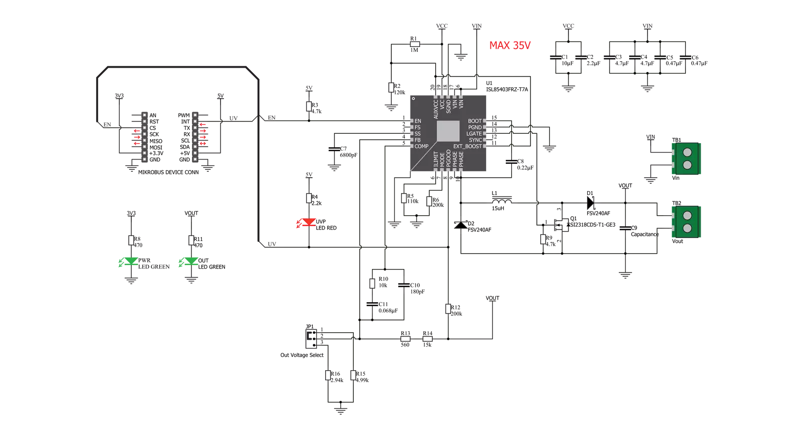
Buck-Boost 3 Click is based on the ISL85403, a 2.5A regulator with the integrated high-side MOSFET and a low-side driver from Renesas, allowing it to be used in different topologies. Buck-Boost 3 Click uses the single inductor buck-boost topology, allowing it to maintain the selected 3.3V or 5V on the output, regardless of the input voltage. The input voltage can vary between about 2.5V and 35V. This makes the Click board™ suitable for the battery power regulator, for example, compensating for the voltage drop while maintaining the constant voltage at the output, which is necessary for the embedded system. The ISL85403 offers two modes of operation: PWM and PFM. These modes are switched automatically depending on the current through the MOSFET, ensuring optimal efficiency for both light and heavier loads at the output. The PFM (Pulse Frequency Modulation) mode allows the ISL85403 to be more efficient when a light load is connected to the output. In this case, the frequency of the PWM oscillator can be dramatically reduced since the stored inductor energy is depleted much slower by the connected load. Although more efficient for light loads, the PFM mode produces a slightly higher output voltage ripple. This makes the PFM mode well-suited for situations when the connected device
enters hibernation or sleep mode. Buck-Boost 3 Click has a resistor that sets the device to operate in PWM mode until the current through the MOSFET drops under 0.4A. The maximum output current depends on many external factors, mostly on heat dissipation, the duty cycle of the internal PWM oscillator, and the input voltage. Since the Buck-Boost 3 click uses a synchronous switching model with the external low-side MOSFET, the heat dissipation is somewhat lowered, but it still depends on the input voltage and the duty cycle. The ISL85403 datasheet offers formulas that can be used to calculate the specific duty cycle for certain input and output voltages and the current through the inductor. Once these values are known, the maximum current available for the load can be calculated, bearing in mind that the inductor current is limited to about 2.75A by the resistor connected between the ILIM pin of the ISL85403 and GND. The output voltage can be selected by positioning the SMD jumper labeled as VOUT SEL to either the 3V3 or 5V position. This jumper is used to select one of two resistor values for the FB pin of the ISL85403 IC. Values of these resistors are calculated so that the Click board™ offers a selection between 3.3V and 5V. Most embedded applications use one of these voltages, so these values are selected accordingly. The
output voltage presence is indicated by an LED indicator labeled OUT on the Click board™. The ISL85403 does not drive this indicator; this LED is supplied with power directly from the output terminal. Following the idea of providing a regulated 3.3V or 5V on the output, the Click board™ is equipped with the Power Good LED indicator. When there is an undervoltage or overvoltage condition, this pin will be asserted to a LOW logic level, allowing the red LED indicator labeled UVP to turn ON. The undervoltage condition indicates that the voltage at the FB pin has dropped below 90% of the reference value, while the overvoltage condition indicates that the voltage at the FB pin has risen above 110% of the reference value, which is 0.8V for the ISL85403 IC. The status of the LED indicator can also be read by the host MCU since the PGOOD pin of the ISL85403 IC is also routed to the INT pin of the mikroBUS™. The Buck-Boost 3 click also features the EN pin, which enables the ISL85403 IC. The buck-boost IC will be enabled when there is a HIGH logic level on this pin. This pin is pulled to a HIGH logic level by an onboard resistor in case this pin is left floating. This pin is routed to the CS pin of the mikroBUS™, allowing the host MCU to control the Buck-Boost 3 Click.

Features overview
Development board
Flip&Click PIC32MZ is a compact development board designed as a complete solution that brings the flexibility of add-on Click boards™ to your favorite microcontroller, making it a perfect starter kit for implementing your ideas. It comes with an onboard 32-bit PIC32MZ microcontroller, the PIC32MZ2048EFH100 from Microchip, four mikroBUS™ sockets for Click board™ connectivity, two USB connectors, LED indicators, buttons, debugger/programmer connectors, and two headers compatible with Arduino-UNO pinout. Thanks to innovative manufacturing technology,
it allows you to build gadgets with unique functionalities and features quickly. Each part of the Flip&Click PIC32MZ development kit contains the components necessary for the most efficient operation of the same board. In addition, there is the possibility of choosing the Flip&Click PIC32MZ programming method, using the chipKIT bootloader (Arduino-style development environment) or our USB HID bootloader using mikroC, mikroBasic, and mikroPascal for PIC32. This kit includes a clean and regulated power supply block through the USB Type-C (USB-C) connector. All communication
methods that mikroBUS™ itself supports are on this board, including the well-established mikroBUS™ socket, user-configurable buttons, and LED indicators. Flip&Click PIC32MZ development kit allows you to create a new application in minutes. Natively supported by Mikroe software tools, it covers many aspects of prototyping thanks to a considerable number of different Click boards™ (over a thousand boards), the number of which is growing every day.

Microcontroller Overview
MCU Card / MCU

Architecture
PIC32
MCU Memory (KB)
2048
Silicon Vendor
Microchip
Pin count
100
RAM (Bytes)
524288
Used MCU Pins
mikroBUS™ mapper
Take a closer look
Click board™ Schematic
Step by step
Project assembly

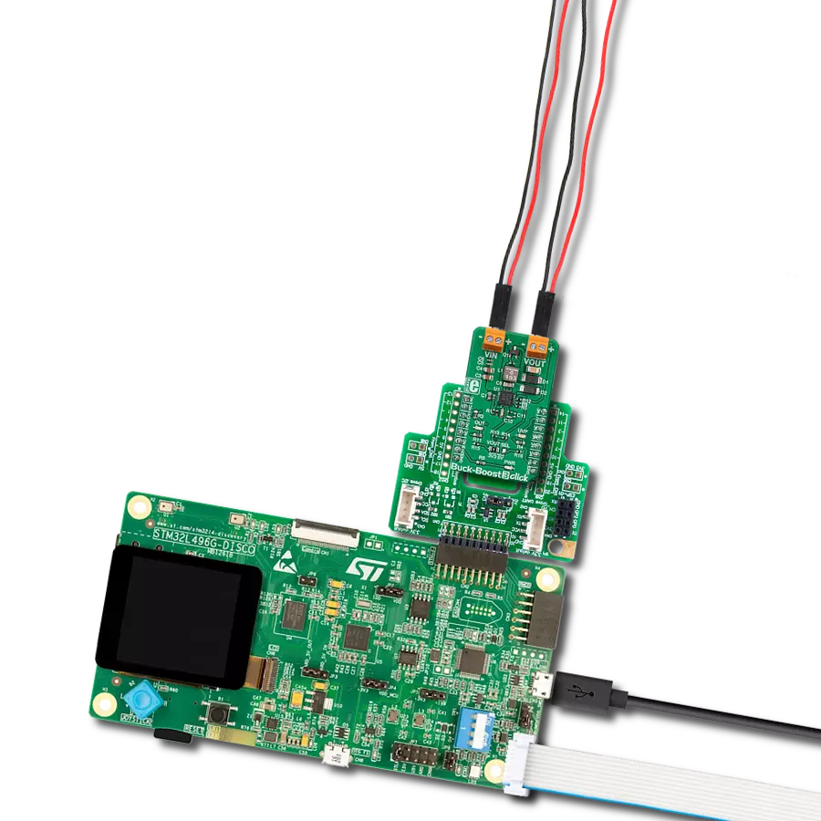
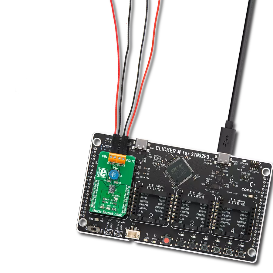
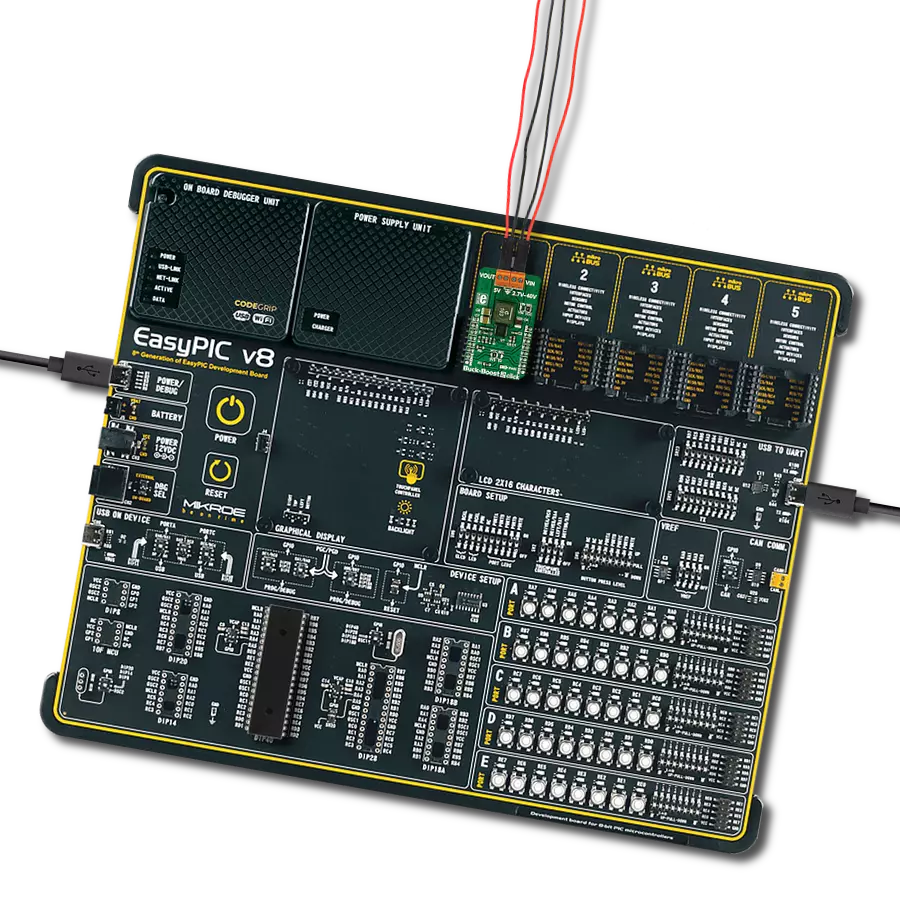
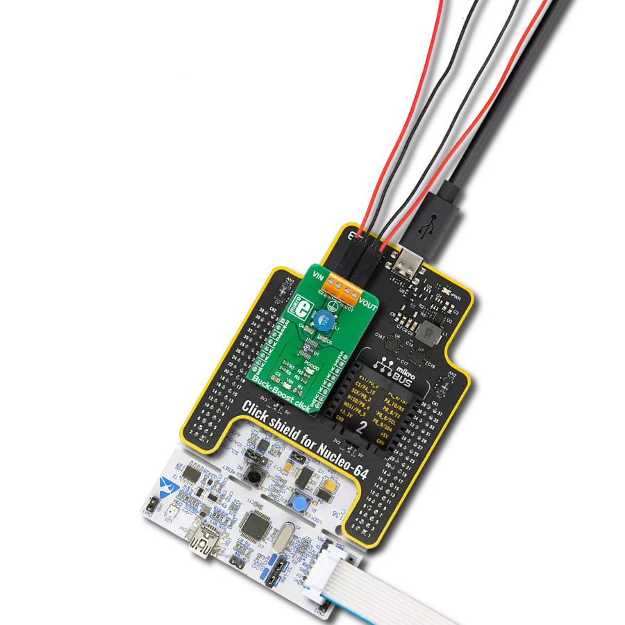
Start by selecting your development board and Click board™. Begin with the Flip&Click PIC32MZ as your development board.


Track your results in real time
Application Output
1. Application Output - In Debug mode, the 'Application Output' window enables real-time data monitoring, offering direct insight into execution results. Ensure proper data display by configuring the environment correctly using the provided tutorial.

2. UART Terminal - Use the UART Terminal to monitor data transmission via a USB to UART converter, allowing direct communication between the Click board™ and your development system. Configure the baud rate and other serial settings according to your project's requirements to ensure proper functionality. For step-by-step setup instructions, refer to the provided tutorial.

3. Plot Output - The Plot feature offers a powerful way to visualize real-time sensor data, enabling trend analysis, debugging, and comparison of multiple data points. To set it up correctly, follow the provided tutorial, which includes a step-by-step example of using the Plot feature to display Click board™ readings. To use the Plot feature in your code, use the function: plot(*insert_graph_name*, variable_name);. This is a general format, and it is up to the user to replace 'insert_graph_name' with the actual graph name and 'variable_name' with the parameter to be displayed.

Software Support
Library Description
This library contains API for Buck-Boost 3 Click driver.
Key functions:
buckboost3_enable- This function enable/disable devicebuckboost3_get_interrupt_state- This function gets intterupt pin state
Open Source
Code example
The complete application code and a ready-to-use project are available through the NECTO Studio Package Manager for direct installation in the NECTO Studio. The application code can also be found on the MIKROE GitHub account.
/*!
 * \file
 * \brief Buck-Boost 3 Click example
 *
 * # Description
 * This application sets buck-boost voltages.
 *
 * The demo application is composed of two sections :
 *
 * ## Application Init
 * Initialization driver init and enable device.
 *
 * ## Application Task
 * It checks if the input voltage is below the operating voltage.
 *
 * \author MikroE Team
 *
 */
// ------------------------------------------------------------------- INCLUDES

#include "board.h"
#include "log.h"
#include "buckboost3.h"

// ------------------------------------------------------------------ VARIABLES

static buckboost3_t buckboost3;
static log_t logger;

// ------------------------------------------------------ APPLICATION FUNCTIONS

void application_init ( void )
{
    log_cfg_t log_cfg;
    buckboost3_cfg_t cfg;

    /**
     * Logger initialization.
     * Default baud rate: 115200
     * Default log level: LOG_LEVEL_DEBUG
     * @note If USB_UART_RX and USB_UART_TX
     * are defined as HAL_PIN_NC, you will
     * need to define them manually for log to work.
     * See @b LOG_MAP_USB_UART macro definition for detailed explanation.
     */
    LOG_MAP_USB_UART( log_cfg );
    log_init( &logger, &log_cfg );
    log_info( &logger, "---- Application Init ----" );

    //  Click initialization.

    buckboost3_cfg_setup( &cfg );
    BUCKBOOST3_MAP_MIKROBUS( cfg, MIKROBUS_1 );
    buckboost3_init( &buckboost3, &cfg );

    buckboost3_enable ( &buckboost3, BUCKBOOST3_DEVICE_ENABLE );
    log_info( &logger, " Device enabled " );
    Delay_ms ( 1000 );
    Delay_ms ( 1000 );
}

void application_task ( void )
{
    if ( !buckboost3_get_interrupt_state( &buckboost3 ) )
    {
        log_error( &logger, " Low input voltage !!!" );
    }
    Delay_ms ( 1000 );
}

int main ( void )
{
    /* Do not remove this line or clock might not be set correctly. */
    #ifdef PREINIT_SUPPORTED
    preinit();
    #endif

    application_init( );

    for ( ; ; )
    {
        application_task( );
    }

    return 0;
}


// ------------------------------------------------------------------------ END
Additional Support
Resources
Category:Buck-Boost