Improve your power management with LTC3129-1 and PIC18F57Q43
Revolutionary voltage control

Published Feb 13, 2024
Click board™
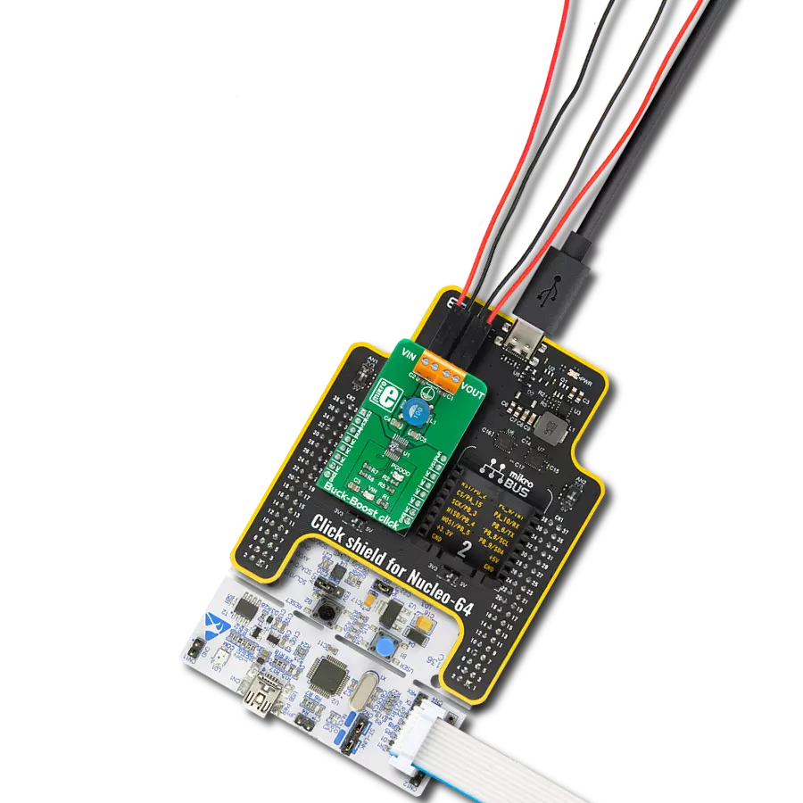
Buck-Boost Click
Dev. board
Curiosity Nano with PIC18F57Q43
Compiler
NECTO Studio
MCU
PIC18F57Q43
Your power, your rules - our Buck-Boost combo empowers you to take charge like never before.
A
A
Hardware Overview
How does it work?
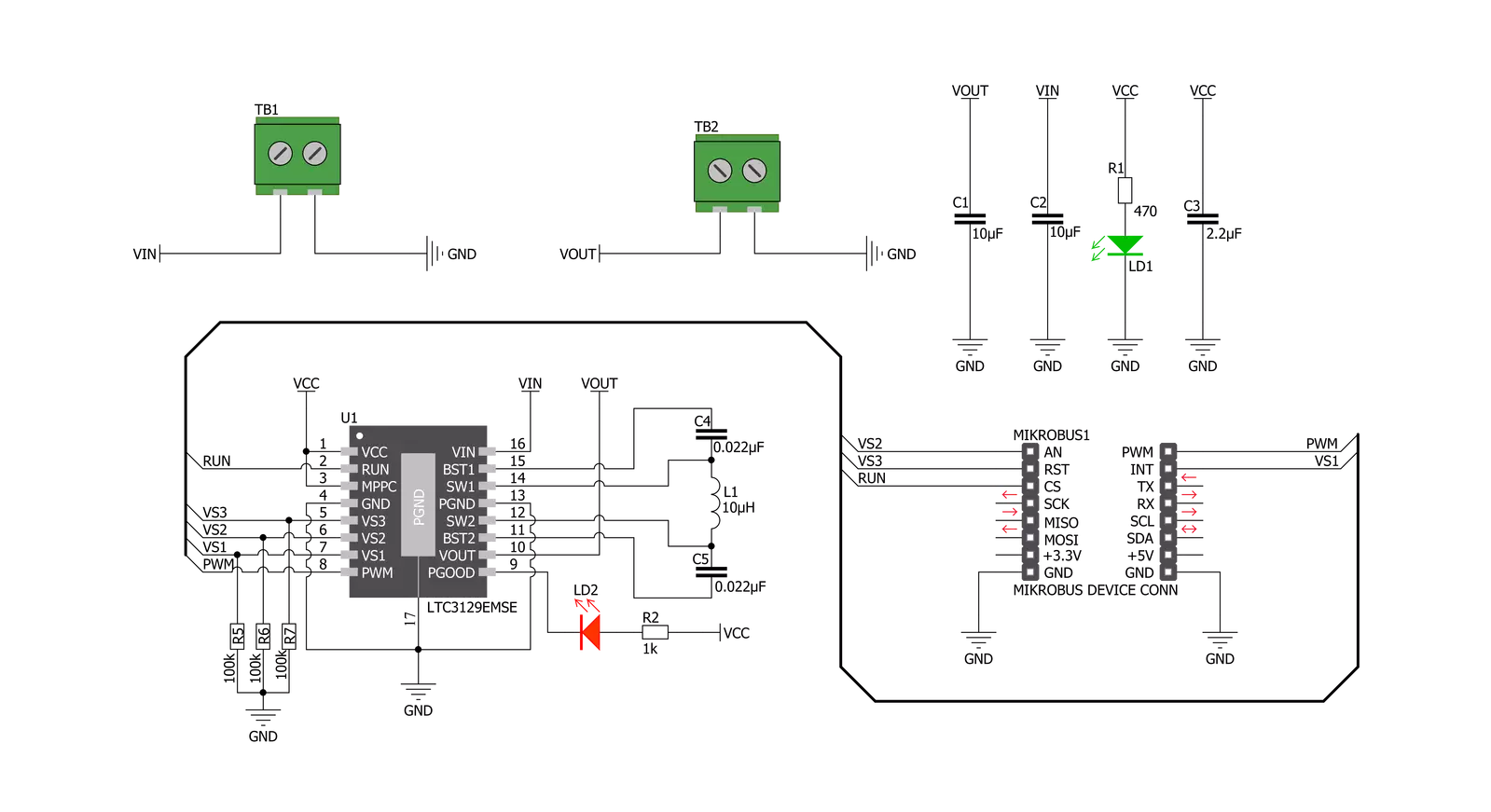
Buck-Boost Click is based on the LTC3129-1, a 1.3μA quiescent current, monolithic, current mode, buck-boost DC/DC converter that can operate over a wide input voltage range of 1.92V to 15V and provide up to 200mA to the load from Analog Devices. The LTC3129-1 is characterized by its low noise and ripple level at the output, high regulating efficiency, and low quiescent current. Eight fixed, user-programmable output voltages can be selected using the three digital programming pins routed to the INT, AN, and CS pins of the mikroBUS™ socket. A proprietary switch control algorithm allows the Buck-Boost converter to regulate output voltage with input voltages above, below, or equal to the output voltage. Transitions between the step-up or step-down operating modes are seamless and free of transients and sub-harmonic switching, making
this product ideal for noise-sensitive applications. Buck-Boost Click possesses two different modes of operation - PWM and Burst Mode, depending on the nature of the application. The PWM mode can be selected by setting the PWM pin of the mikroBUS™ socket to a logic high level and is suitable for working with higher loads connected to the converter output and when extremely low output noise is required. When selecting the PWM mode, LTC3129-1 has a fixed nominal switching frequency of 1.2MHz using an internally compensated average current mode control loop. In this mode, the output voltage's ripple and noise level are minimal. For high-efficiency operation at light loads, automatic Burst Mode operation can be selected, reducing the quiescent current to 1.3µA. Burst mode can be chosen if the PWM pin is set to a logic low level. If the connected load is
light enough, the converter will remain working in Burst mode, running only when necessary to maintain voltage regulation. Otherwise, the PWM mode will automatically engage, providing enough current for the connected load. This Click board™ completely powers itself from the VIN external power supply terminal. Once the power is applied to the VIN terminal, the circuit must also be enabled by setting the RUN pin routed to the RST pin of the mikroBUS™ socket to a high logic level. This will power up the converter, which the PWR LED indicator will indicate. It also includes additional features such as a power-good output with a Power Good LED indicator labeled PGOOD that pulls to the ground when FB drops too far below its regulated voltage. This pin also can sink up to the absolute maximum rating of 15mA when set low.

Features overview
Development board
PIC18F57Q43 Curiosity Nano evaluation kit is a cutting-edge hardware platform designed to evaluate microcontrollers within the PIC18-Q43 family. Central to its design is the inclusion of the powerful PIC18F57Q43 microcontroller (MCU), offering advanced functionalities and robust performance. Key features of this evaluation kit include a yellow user LED and a responsive
mechanical user switch, providing seamless interaction and testing. The provision for a 32.768kHz crystal footprint ensures precision timing capabilities. With an onboard debugger boasting a green power and status LED, programming and debugging become intuitive and efficient. Further enhancing its utility is the Virtual serial port (CDC) and a debug GPIO channel (DGI
GPIO), offering extensive connectivity options. Powered via USB, this kit boasts an adjustable target voltage feature facilitated by the MIC5353 LDO regulator, ensuring stable operation with an output voltage ranging from 1.8V to 5.1V, with a maximum output current of 500mA, subject to ambient temperature and voltage constraints.

Microcontroller Overview
MCU Card / MCU

Architecture
PIC
MCU Memory (KB)
128
Silicon Vendor
Microchip
Pin count
48
RAM (Bytes)
8196
You complete me!
Accessories
Curiosity Nano Base for Click boards is a versatile hardware extension platform created to streamline the integration between Curiosity Nano kits and extension boards, tailored explicitly for the mikroBUS™-standardized Click boards and Xplained Pro extension boards. This innovative base board (shield) offers seamless connectivity and expansion possibilities, simplifying experimentation and development. Key features include USB power compatibility from the Curiosity Nano kit, alongside an alternative external power input option for enhanced flexibility. The onboard Li-Ion/LiPo charger and management circuit ensure smooth operation for battery-powered applications, simplifying usage and management. Moreover, the base incorporates a fixed 3.3V PSU dedicated to target and mikroBUS™ power rails, alongside a fixed 5.0V boost converter catering to 5V power rails of mikroBUS™ sockets, providing stable power delivery for various connected devices.

Used MCU Pins
mikroBUS™ mapper
Take a closer look
Click board™ Schematic
Step by step
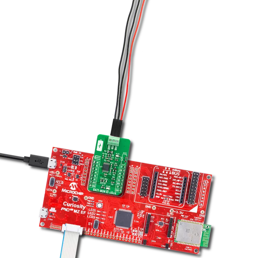
Project assembly

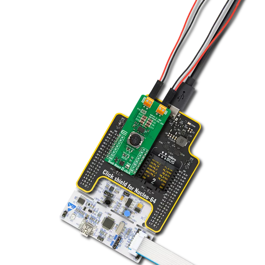
Start by selecting your development board and Click board™. Begin with the Curiosity Nano with PIC18F57Q43 as your development board.


Software Support
Library Description
This library contains API for Buck-Boost Click driver.
Key functions:
buckboost_set_mode_fixed_freq- This function set fixed frequency PWM operation mode of LTC3129-1buckboost_enables_auto_burst_mode- This function enables automatic burst mode operation of LTC3129-1buckboost_set_2500mv- This function set the output voltage of 2500mV
Open Source
Code example
The complete application code and a ready-to-use project are available through the NECTO Studio Package Manager for direct installation in the NECTO Studio. The application code can also be found on the MIKROE GitHub account.
/*!
 * \file
 * \brief Buck-Boost  Click example
 *
 * # Description
 * The demo application change output voltage from 2500 mV to 15000 mV every 5 seconds.
 *
 * The demo application is composed of two sections :
 *
 * ## Application Init
 * Initialization device and set default configuration.
 *
 * ## Application Task
 *  This is a example which demonstrates the use of Buck Boost Click board.
 *  Change output voltage from 2500 mV to 15000 mV every 5 seconds.
 *  All data logs write on usb uart for aproximetly every 5 sec.
 *
 * \author MikroE Team
 *
 */
// ------------------------------------------------------------------- INCLUDES

#include "board.h"
#include "log.h"
#include "buckboost.h"

// ------------------------------------------------------------------ VARIABLES

static buckboost_t buckboost;
static log_t logger;

// ------------------------------------------------------ APPLICATION FUNCTIONS

void application_init ( void )
{
    log_cfg_t log_cfg;
    buckboost_cfg_t cfg;

    /**
     * Logger initialization.
     * Default baud rate: 115200
     * Default log level: LOG_LEVEL_DEBUG
     * @note If USB_UART_RX and USB_UART_TX
     * are defined as HAL_PIN_NC, you will
     * need to define them manually for log to work.
     * See @b LOG_MAP_USB_UART macro definition for detailed explanation.
     */
    LOG_MAP_USB_UART( log_cfg );
    log_init( &logger, &log_cfg );
    log_info(&logger, "---- Application Init ----\r\n");

    //  Click initialization.

    buckboost_cfg_setup( &cfg );
    BUCKBOOST_MAP_MIKROBUS( cfg, MIKROBUS_1 );
    buckboost_init( &buckboost, &cfg );

    buckboost_default_cfg( &buckboost );
    log_printf( &logger, "--------------------------------\r\n" );
    log_printf( &logger, "        Buck Boost Click        \r\n" );
    log_printf( &logger, "--------------------------------\r\n" );
    Delay_ms ( 100 );
}

void application_task ( void )
{
    log_printf( &logger, " Set Output Voltage of  2500 mV \r\n" );
    log_printf( &logger, "--------------------------------\r\n" );
    buckboost_set_2500mv( &buckboost );
    Delay_ms ( 1000 );
    Delay_ms ( 1000 );
    Delay_ms ( 1000 );
    Delay_ms ( 1000 );
    Delay_ms ( 1000 );

    log_printf( &logger, " Set Output Voltage of  3300 mV \r\n" );
    log_printf( &logger, "--------------------------------\r\n" );
    buckboost_set_3300mv( &buckboost );
    Delay_ms ( 1000 );
    Delay_ms ( 1000 );
    Delay_ms ( 1000 );
    Delay_ms ( 1000 );
    Delay_ms ( 1000 );

    log_printf( &logger, " Set Output Voltage of  4100 mV \r\n" );
    log_printf( &logger, "--------------------------------\r\n" );
    buckboost_set_4100mv( &buckboost );
    Delay_ms ( 1000 );
    Delay_ms ( 1000 );
    Delay_ms ( 1000 );
    Delay_ms ( 1000 );
    Delay_ms ( 1000 );

    log_printf( &logger, " Set Output Voltage of  5000 mV \r\n" );
    log_printf( &logger, "--------------------------------\r\n" );
    buckboost_set_5000mv( &buckboost );
    Delay_ms ( 1000 );
    Delay_ms ( 1000 );
    Delay_ms ( 1000 );
    Delay_ms ( 1000 );
    Delay_ms ( 1000 );

    log_printf( &logger, " Set Output Voltage of  6900 mV \r\n" );
    log_printf( &logger, "--------------------------------\r\n" );
    buckboost_set_6900mv( &buckboost );
    Delay_ms ( 1000 );
    Delay_ms ( 1000 );
    Delay_ms ( 1000 );
    Delay_ms ( 1000 );
    Delay_ms ( 1000 );

    log_printf( &logger, " Set Output Voltage of  8200 mV \r\n" );
    log_printf( &logger, "--------------------------------\r\n" );
    buckboost_set_8200mv( &buckboost );
    Delay_ms ( 1000 );
    Delay_ms ( 1000 );
    Delay_ms ( 1000 );
    Delay_ms ( 1000 );
    Delay_ms ( 1000 );

    log_printf( &logger, " Set Output Voltage of  12000 mV \r\n" );
    log_printf( &logger, "--------------------------------\r\n" );
    buckboost_set_12000mv( &buckboost );
    Delay_ms ( 1000 );
    Delay_ms ( 1000 );
    Delay_ms ( 1000 );
    Delay_ms ( 1000 );
    Delay_ms ( 1000 );

    log_printf( &logger, " Set Output Voltage of  15000 mV \r\n" );
    log_printf( &logger, "--------------------------------\r\n" );
    buckboost_set_15000mv( &buckboost );
    Delay_ms ( 1000 );
    Delay_ms ( 1000 );
    Delay_ms ( 1000 );
    Delay_ms ( 1000 );
    Delay_ms ( 1000 );
}

int main ( void )
{
    /* Do not remove this line or clock might not be set correctly. */
    #ifdef PREINIT_SUPPORTED
    preinit();
    #endif

    application_init( );

    for ( ; ; )
    {
        application_task( );
    }

    return 0;
}

// ------------------------------------------------------------------------ END
Additional Support
Resources
Category:Buck-Boost