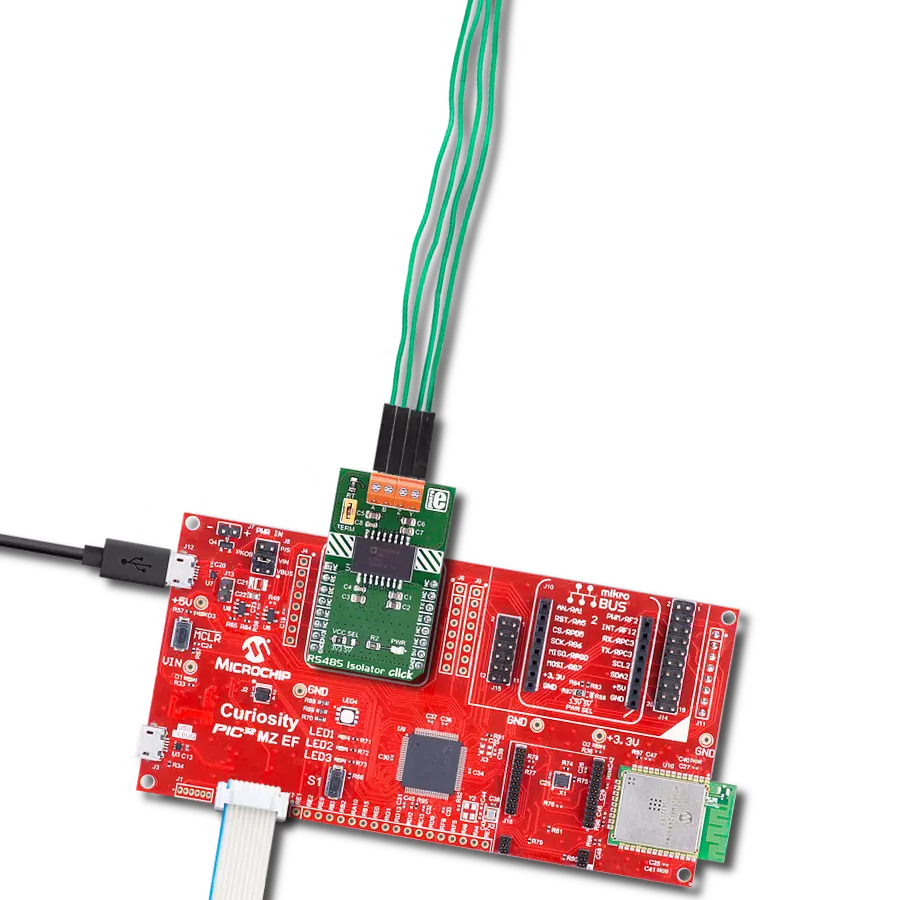
Provide galvanic isolation between the transmitter and receiver for enhanced electrical safety with ISO1450 and PIC32MZ2048EFH100
5kVRMS isolated half-duplex RS-485 transceiver

Published Nov 06, 2024
Click board™
RS485 Isolator 4 Click
Dev. board
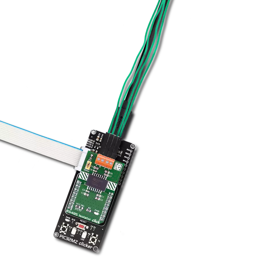
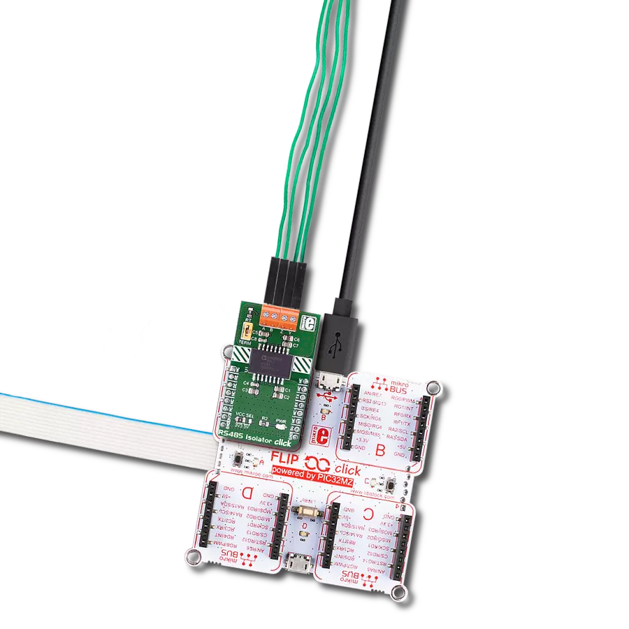
Flip&Click PIC32MZ
Compiler
NECTO Studio
MCU
PIC32MZ2048EFH100
Reliable, isolated RS-485 communication with robust protection for industrial environments like grid infrastructure, motor drives, and building automation
A
A
Hardware Overview
How does it work?
RS485 Isolator 4 Click is based on the ISO1450, an isolated half-duplex RS-485 transceiver from Texas Instruments. This transceiver is designed to provide galvanic isolation for RS-485 and RS-422 communication, offering robust noise immunity essential for harsh industrial environments. The ISO1450's bus pins are engineered to withstand high levels of electrostatic discharge (ESD) and electrical fast transients (EFT), eliminating the need for additional external components to ensure system-level protection. This capability makes the Click board™ ideal for industrial and commercial communication needs such as grid infrastructure, solar inverters, motor drives, HVAC systems, and building automation. With support for data rates up to 50Mbps, the ISO1450 enables long-distance communication while maintaining signal integrity. Its silicon-dioxide capacitive isolation barrier
provides a reliable 5kVRMS isolation for 1 minute, as per UL 1577 standards, and a working voltage of 1500VPK. This isolation feature breaks ground loops between communicating nodes, allowing a wider common-mode voltage range. The ISO1450's isolated side can operate over a broad supply voltage range of 3V to 5.5V, removing the need for a regulated supply on this side. The ISO1450 also includes advanced failsafe features to protect against invalid bus states, such as open bus conditions from broken cables, shorted bus conditions due to insulation breakdowns, and idle bus conditions where no driver is actively transmitting. This ensures reliable operation, even when communication lines encounter physical issues. In addition to the standard UART interface TX and RX pins from the mikroBUS™ socket, RS485 Isolator 4 Click also features receiver and
driver enable pins, routed to the RE and DE pins of the mikroBUS™. In this half-duplex implementation, the driver and receiver enable pins allow any connected node on the J1 header to be configured as either transmitting or receiving at any given moment. This flexibility reduces the need for additional cables since it allows dynamic switching between transmit and receive modes on the same communication line. This Click board™ can operate with either 3.3V or 5V logic voltage levels selected via the VCC SEL jumper. This way, both 3.3V and 5V capable MCUs can use the communication lines properly. Also, this Click board™ comes equipped with a library containing easy-to-use functions and an example code that can be used as a reference for further development.

Features overview
Development board
Flip&Click PIC32MZ is a compact development board designed as a complete solution that brings the flexibility of add-on Click boards™ to your favorite microcontroller, making it a perfect starter kit for implementing your ideas. It comes with an onboard 32-bit PIC32MZ microcontroller, the PIC32MZ2048EFH100 from Microchip, four mikroBUS™ sockets for Click board™ connectivity, two USB connectors, LED indicators, buttons, debugger/programmer connectors, and two headers compatible with Arduino-UNO pinout. Thanks to innovative manufacturing technology,
it allows you to build gadgets with unique functionalities and features quickly. Each part of the Flip&Click PIC32MZ development kit contains the components necessary for the most efficient operation of the same board. In addition, there is the possibility of choosing the Flip&Click PIC32MZ programming method, using the chipKIT bootloader (Arduino-style development environment) or our USB HID bootloader using mikroC, mikroBasic, and mikroPascal for PIC32. This kit includes a clean and regulated power supply block through the USB Type-C (USB-C) connector. All communication
methods that mikroBUS™ itself supports are on this board, including the well-established mikroBUS™ socket, user-configurable buttons, and LED indicators. Flip&Click PIC32MZ development kit allows you to create a new application in minutes. Natively supported by Mikroe software tools, it covers many aspects of prototyping thanks to a considerable number of different Click boards™ (over a thousand boards), the number of which is growing every day.

Microcontroller Overview
MCU Card / MCU

Architecture
PIC32
MCU Memory (KB)
2048
Silicon Vendor
Microchip
Pin count
100
RAM (Bytes)
524288
You complete me!
Accessories
Wire Jumpers Male to Male (15 cm length, 10pcs) is a set of high-quality jumper wires designed for easy prototyping and testing. Each wire in the set is 15cm long, with male connectors on both ends, allowing an easy connection between components on breadboards or other electronic projects. The set includes ten wires in different colors, providing clear identification and organization in your circuit. These wire jumpers are ideal for DIY projects, setups, and other electronic applications where quick, reliable connections are required.

Used MCU Pins
mikroBUS™ mapper
Take a closer look
Click board™ Schematic

Step by step
Project assembly

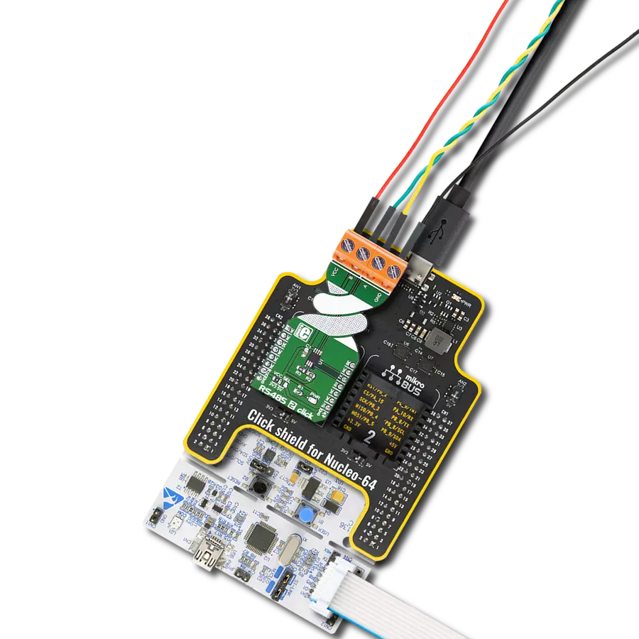
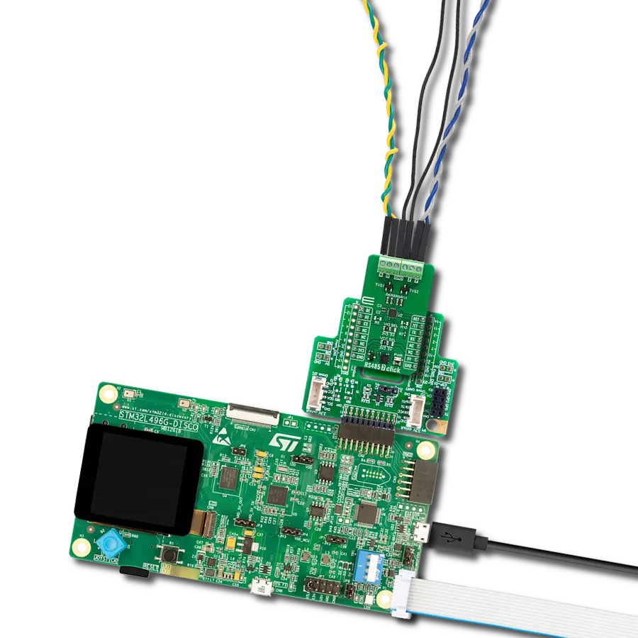
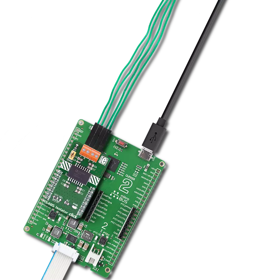
Start by selecting your development board and Click board™. Begin with the Flip&Click PIC32MZ as your development board.


Track your results in real time
Application Output
1. Application Output - In Debug mode, the 'Application Output' window enables real-time data monitoring, offering direct insight into execution results. Ensure proper data display by configuring the environment correctly using the provided tutorial.

2. UART Terminal - Use the UART Terminal to monitor data transmission via a USB to UART converter, allowing direct communication between the Click board™ and your development system. Configure the baud rate and other serial settings according to your project's requirements to ensure proper functionality. For step-by-step setup instructions, refer to the provided tutorial.

3. Plot Output - The Plot feature offers a powerful way to visualize real-time sensor data, enabling trend analysis, debugging, and comparison of multiple data points. To set it up correctly, follow the provided tutorial, which includes a step-by-step example of using the Plot feature to display Click board™ readings. To use the Plot feature in your code, use the function: plot(*insert_graph_name*, variable_name);. This is a general format, and it is up to the user to replace 'insert_graph_name' with the actual graph name and 'variable_name' with the parameter to be displayed.

Software Support
Library Description
This library contains API for RS485 Isolator 4 Click driver.
Key functions:
rs485isolator4_generic_write- This function writes a desired number of data bytes by using UART serial interface.rs485isolator4_generic_read- This function reads a desired number of data bytes by using UART serial interface.rs485isolator4_driver_enable- This function enables the driver input by setting the DE pin to high logic state.
Open Source
Code example
The complete application code and a ready-to-use project are available through the NECTO Studio Package Manager for direct installation in the NECTO Studio. The application code can also be found on the MIKROE GitHub account.
/*!
 * @file main.c
 * @brief RS485 Isolator 4 Click Example.
 *
 * # Description
 * This example demonstrates the use of an RS485 Isolator 4 Click board by showing
 * the communication between the two Click board configured as a receiver and transmitter.
 *
 * The demo application is composed of two sections :
 *
 * ## Application Init
 * Initializes the driver and logger and displays the selected application mode.
 *
 * ## Application Task
 * Depending on the selected mode, it reads all the received data or sends the desired
 * message every 2 seconds.
 *
 * @note
 * Make sure to provide a power supply voltage to isolated VCC_EXT and GND pins
 * in a range from 3V to 5.5V.
 *
 * @author Stefan Filipovic
 *
 */

#include "board.h"
#include "log.h"
#include "rs485isolator4.h"

// Comment out the line below in order to switch the application mode to receiver
#define DEMO_APP_TRANSMITTER

#define DEMO_TEXT_MESSAGE   "MIKROE - RS485 Isolator 4 Click board\r\n"

static rs485isolator4_t rs485isolator4;
static log_t logger;

void application_init ( void )
{
    log_cfg_t log_cfg;  /**< Logger config object. */
    rs485isolator4_cfg_t rs485isolator4_cfg;  /**< Click config object. */

    /**
     * Logger initialization.
     * Default baud rate: 115200
     * Default log level: LOG_LEVEL_DEBUG
     * @note If USB_UART_RX and USB_UART_TX
     * are defined as HAL_PIN_NC, you will
     * need to define them manually for log to work.
     * See @b LOG_MAP_USB_UART macro definition for detailed explanation.
     */
    LOG_MAP_USB_UART( log_cfg );
    log_init( &logger, &log_cfg );
    log_info( &logger, " Application Init " );

    // Click initialization.
    rs485isolator4_cfg_setup( &rs485isolator4_cfg );
    RS485ISOLATOR4_MAP_MIKROBUS( rs485isolator4_cfg, MIKROBUS_1 );
    if ( UART_ERROR == rs485isolator4_init( &rs485isolator4, &rs485isolator4_cfg ) )
    {
        log_error( &logger, " Communication init." );
        for ( ; ; );
    }

#ifdef DEMO_APP_TRANSMITTER
    rs485isolator4_driver_enable ( &rs485isolator4 );
    rs485isolator4_receiver_disable ( &rs485isolator4 );
    log_printf( &logger, " Application Mode: Transmitter\r\n" );
#else
    rs485isolator4_driver_disable ( &rs485isolator4 );
    rs485isolator4_receiver_enable ( &rs485isolator4 );
    log_printf( &logger, " Application Mode: Receiver\r\n" );
#endif
    log_info( &logger, " Application Task " );
}

void application_task ( void )
{
#ifdef DEMO_APP_TRANSMITTER
    rs485isolator4_generic_write( &rs485isolator4, DEMO_TEXT_MESSAGE, strlen( DEMO_TEXT_MESSAGE ) );
    log_printf( &logger, "%s", ( char * ) DEMO_TEXT_MESSAGE );
    Delay_ms( 1000 );
    Delay_ms( 1000 );
#else
    uint8_t rx_data = 0;
    if ( rs485isolator4_generic_read( &rs485isolator4, &rx_data, 1 ) > 0 )
    {
        log_printf( &logger, "%c", rx_data );
    }
#endif
}

int main ( void )
{
    /* Do not remove this line or clock might not be set correctly. */
    #ifdef PREINIT_SUPPORTED
    preinit();
    #endif

    application_init( );

    for ( ; ; )
    {
        application_task( );
    }

    return 0;
}

// ------------------------------------------------------------------------ END
Additional Support
Resources
Category:RS485