Bid farewell to frustrating volume fluctuations thanks to NJU72341 and PIC32MZ2048EFH100 combo solution
Experience audio nirvana: Your volume, your way

Published Oct 22, 2023
Click board™
Volume 2 Click
Dev. board
Flip&Click PIC32MZ
Compiler
NECTO Studio
MCU
PIC32MZ2048EFH100
Experience a higher level of audio quality and precision with our volume control device, which enhances clarity and fidelity for a more immersive listening experience
A
A
Hardware Overview
How does it work?
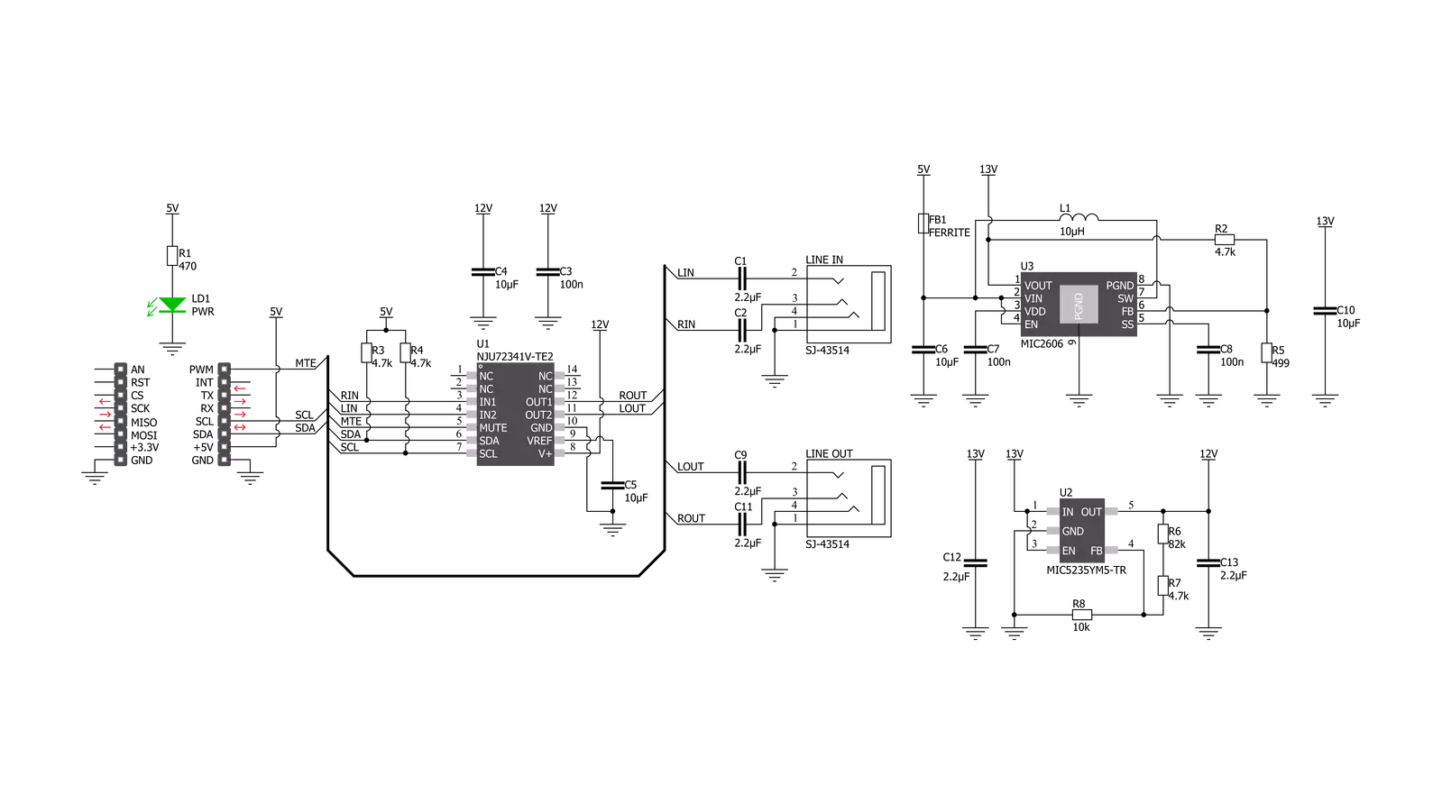
Volume 2 Click is based on the NJU72341, a 2-channel I2C configurable electronic volume IC with an external mute control from JRC. The NJU72341 operates as an audio signal processor with many characteristics useful in an audio application, such as low noise typical of 2.0µVrms and low distortion of 0.002%. It controls two independent audio channels with a vast volume control range from 0 to 95dB with 1dB step offering zero-cross detection to protect against pop noise. This Click board™ is suitable for stereo and multi-channel audio systems. The NJU72341 has to receive a specific supply voltage to operate
appropriately, in this case, 12V. Unlike the Volume Click, which has a symmetrical power supply, we have only one positive power supply in this case. Bringing just a positive power supply, the noise generated by that power supply will transmit to the output, representing a side effect. For this purpose, Volume 2 Click employs a boost converter unit that combines MIC5235 and MIC2606, both from Microchip. MIC5235 provides 13V out of 5V from the mikroBUS™ power rail, which then the MIC2606, with a feature of massive noise suppression, lowers it to 12V and then supplies NJU72341, reducing the noise generated
at its output. Volume 2 Click communicates with MCU using a standard I2C 2-Wire interface, with a clock frequency up to 100kHz in the Standard and 400kHz in the Fast Mode. Also, the user can have external mute control configurable through the PWM pin of the mikroBUS™ socket labeled as MTE. This Click board™ can be operated only with a 5V logic voltage level. The board must perform appropriate logic voltage level conversion before using MCUs with different logic levels. Also, it comes equipped with a library containing functions and an example code that can be used as a reference for further development.


Features overview
Development board
Flip&Click PIC32MZ is a compact development board designed as a complete solution that brings the flexibility of add-on Click boards™ to your favorite microcontroller, making it a perfect starter kit for implementing your ideas. It comes with an onboard 32-bit PIC32MZ microcontroller, the PIC32MZ2048EFH100 from Microchip, four mikroBUS™ sockets for Click board™ connectivity, two USB connectors, LED indicators, buttons, debugger/programmer connectors, and two headers compatible with Arduino-UNO pinout. Thanks to innovative manufacturing technology,
it allows you to build gadgets with unique functionalities and features quickly. Each part of the Flip&Click PIC32MZ development kit contains the components necessary for the most efficient operation of the same board. In addition, there is the possibility of choosing the Flip&Click PIC32MZ programming method, using the chipKIT bootloader (Arduino-style development environment) or our USB HID bootloader using mikroC, mikroBasic, and mikroPascal for PIC32. This kit includes a clean and regulated power supply block through the USB Type-C (USB-C) connector. All communication
methods that mikroBUS™ itself supports are on this board, including the well-established mikroBUS™ socket, user-configurable buttons, and LED indicators. Flip&Click PIC32MZ development kit allows you to create a new application in minutes. Natively supported by Mikroe software tools, it covers many aspects of prototyping thanks to a considerable number of different Click boards™ (over a thousand boards), the number of which is growing every day.

Microcontroller Overview
MCU Card / MCU

Architecture
PIC32
MCU Memory (KB)
2048
Silicon Vendor
Microchip
Pin count
100
RAM (Bytes)
524288
Used MCU Pins
mikroBUS™ mapper
Take a closer look
Click board™ Schematic
Step by step
Project assembly

Start by selecting your development board and Click board™. Begin with the Flip&Click PIC32MZ as your development board.


Track your results in real time
Application Output
1. Application Output - In Debug mode, the 'Application Output' window enables real-time data monitoring, offering direct insight into execution results. Ensure proper data display by configuring the environment correctly using the provided tutorial.

2. UART Terminal - Use the UART Terminal to monitor data transmission via a USB to UART converter, allowing direct communication between the Click board™ and your development system. Configure the baud rate and other serial settings according to your project's requirements to ensure proper functionality. For step-by-step setup instructions, refer to the provided tutorial.

3. Plot Output - The Plot feature offers a powerful way to visualize real-time sensor data, enabling trend analysis, debugging, and comparison of multiple data points. To set it up correctly, follow the provided tutorial, which includes a step-by-step example of using the Plot feature to display Click board™ readings. To use the Plot feature in your code, use the function: plot(*insert_graph_name*, variable_name);. This is a general format, and it is up to the user to replace 'insert_graph_name' with the actual graph name and 'variable_name' with the parameter to be displayed.

Software Support
Library Description
This library contains API for Volume 2 Click driver.
Key functions:
volume2_update_vol_data- This function updates the volume by using direct defined structure optionsvolume2_device_mute- This function is used to set mute on or off by controlling the mte pinvolume2_generic_write- This function writes a desired number of data bytes starting from the selected register by using I2C serial interface
Open Source
Code example
The complete application code and a ready-to-use project are available through the NECTO Studio Package Manager for direct installation in the NECTO Studio. The application code can also be found on the MIKROE GitHub account.
/*!
 * @file main.c
 * @brief Volume2 Click example
 *
 * # Description
 * This example shows how Volume 2 Click board can be used
 * for controlling the audio channels. Thanks to this, a
 * simple audio effect is created by switching volume from
 * right to left and vice versa.
 *
 * The demo application is composed of two sections :
 *
 * ## Application Init
 * UART LOG and I2C drivers are initialized, following the
 * default configuration. By default, both channels are set
 * to 9 dB gain with zero cross detection enabled.
 *
 * ## Application Task
 * The task performs and effect of switching the volume
 * from right to left channel and vice versa. Like playing
 * ping-pong with the sound.
 *
 * @author Stefan Nikolic
 *
 */

#include "board.h"
#include "log.h"
#include "volume2.h"

static volume2_t volume2;
static log_t logger;

static volume2_vol_data_t volume_upd_data;
static uint8_t rising_vol;
static uint8_t max_atten = 60;

void application_init ( void ) {
    log_cfg_t log_cfg;          /**< Logger config object. */
    volume2_cfg_t volume2_cfg;  /**< Click config object. */

    /**
     * Logger initialization.
     * Default baud rate: 115200
     * Default log level: LOG_LEVEL_DEBUG
     * @note If USB_UART_RX and USB_UART_TX
     * are defined as HAL_PIN_NC, you will
     * need to define them manually for log to work.
     * See @b LOG_MAP_USB_UART macro definition for detailed explanation.
     */
    LOG_MAP_USB_UART( log_cfg );
    log_init( &logger, &log_cfg );
    log_info( &logger, " Application Init " );

    // Click initialization.

    volume2_cfg_setup( &volume2_cfg );
    VOLUME2_MAP_MIKROBUS( volume2_cfg, MIKROBUS_1 );
    err_t init_flag = volume2_init( &volume2, &volume2_cfg );
    if ( init_flag == I2C_MASTER_ERROR ) {
        log_error( &logger, " Application Init Error. " );
        log_info( &logger, " Please, run program again... " );

        for ( ; ; );
    }

    volume2_default_cfg( &volume2 );
    Delay_ms ( 100 );
    log_info( &logger, " Application Task " );
}

void application_task ( void ) {
    for ( rising_vol = 0 ; rising_vol < max_atten ; rising_vol++ ) {
        volume_upd_data.attenuation_ch1 = rising_vol;
        volume_upd_data.attenuation_ch2 = max_atten - rising_vol;
        volume2_update_vol_data( &volume2, volume_upd_data );
        Delay_ms ( 50 );
    }
    Delay_ms ( 1000 );
    for ( rising_vol = 0 ; rising_vol < max_atten ; rising_vol++ ) {
        volume_upd_data.attenuation_ch1 = max_atten - rising_vol;
        volume_upd_data.attenuation_ch2 = rising_vol;
        volume2_update_vol_data( &volume2, volume_upd_data );
        Delay_ms ( 50 );
    }
    Delay_ms ( 1000 );
}

int main ( void )
{
    /* Do not remove this line or clock might not be set correctly. */
    #ifdef PREINIT_SUPPORTED
    preinit();
    #endif

    application_init( );

    for ( ; ; )
    {
        application_task( );
    }

    return 0;
}

// ------------------------------------------------------------------------ END