Create simple sounds including beeps and buzzers with PAM8906 and PIC32MZ2048EFH100
Piezoelectric sounder

Published Dec 10, 2023
Click board™
Piezo Driver Click
Dev. board
Flip&Click PIC32MZ
Compiler
NECTO Studio
MCU
PIC32MZ2048EFH100
Convert electrical energy into mechanical vibrations and produce audible sound waves
A
A
Hardware Overview
How does it work?
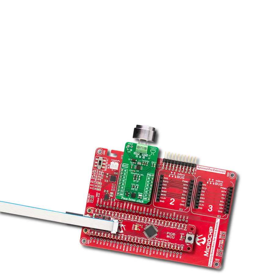
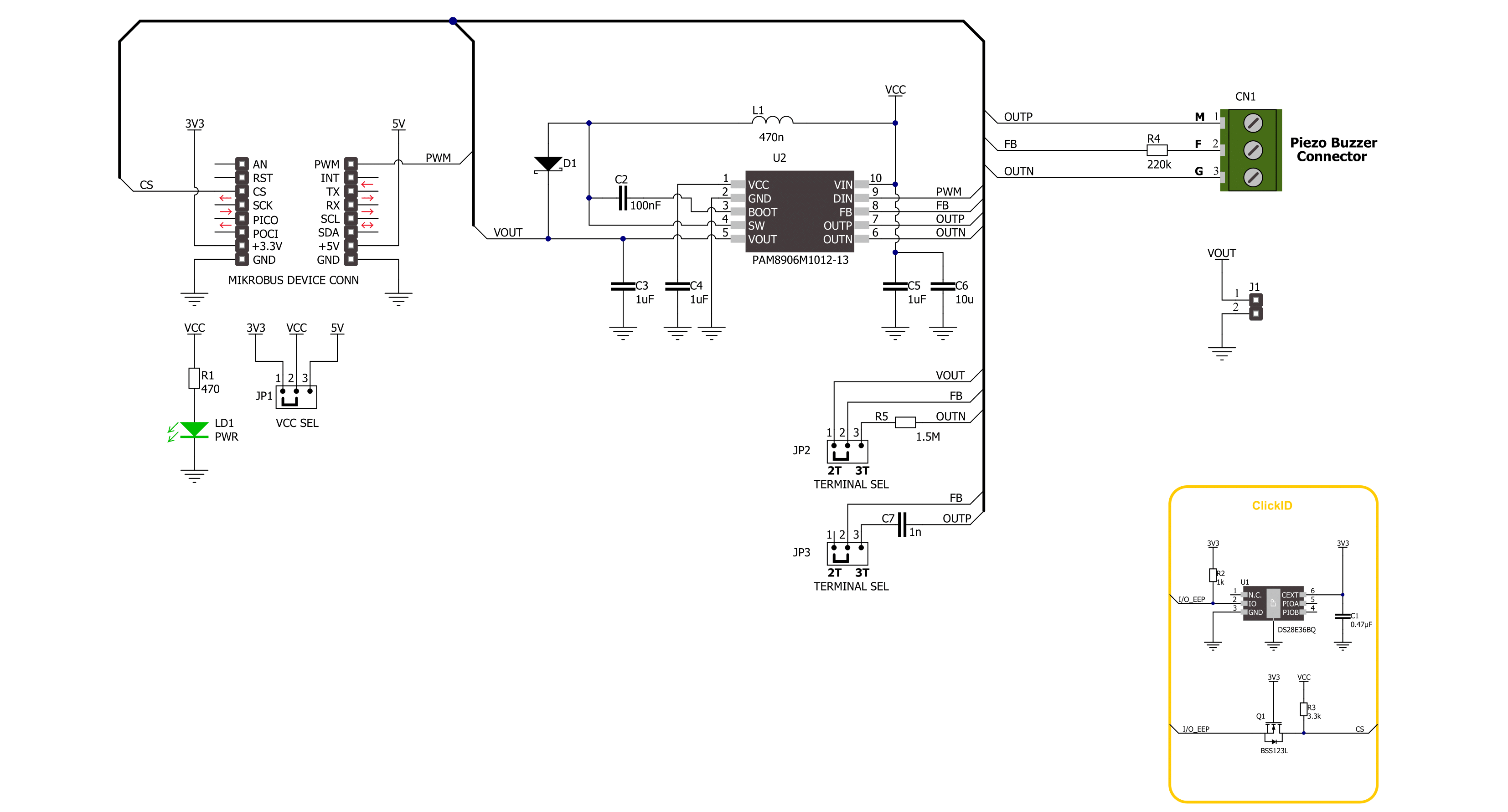
Piezo Driver Click is based on the PAM8906, a piezo sounder driver with self-excitation mode from Diodes Incorporated. It features automatic shutdown and wake-up control, low operating current, very short turn ON/OFF, over-voltage protection, over-current protection, and more. This driver operates with an external PWM input. It can drive a two-terminal or three-terminal piezo sounder, and selection can be made over the
TERMINAL SEL jumper. The piezo sounder can be connected over the 3-pin screw terminal, labeled differently for both available options. In addition, you can use VOUT to power up the piezo sounder. Piezo Driver Click uses a PWM input pin to communicate with the host MCU. The PWM input will be amplified and driven to the output terminal if used as an external PWM control. It can also be used for automatic wake-up and shutdown
control. This Click board™ can operate with either 3.3V or 5V logic voltage levels selected via the VCC SEL jumper. This way, both 3.3V and 5V capable MCUs can use the communication lines properly. Also, this Click board™ comes equipped with a library containing easy-to-use functions and an example code that can be used as a reference for further development.

Features overview
Development board
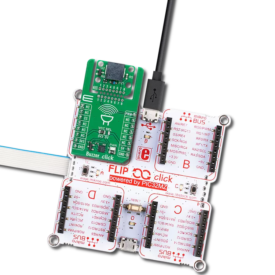
Flip&Click PIC32MZ is a compact development board designed as a complete solution that brings the flexibility of add-on Click boards™ to your favorite microcontroller, making it a perfect starter kit for implementing your ideas. It comes with an onboard 32-bit PIC32MZ microcontroller, the PIC32MZ2048EFH100 from Microchip, four mikroBUS™ sockets for Click board™ connectivity, two USB connectors, LED indicators, buttons, debugger/programmer connectors, and two headers compatible with Arduino-UNO pinout. Thanks to innovative manufacturing technology,
it allows you to build gadgets with unique functionalities and features quickly. Each part of the Flip&Click PIC32MZ development kit contains the components necessary for the most efficient operation of the same board. In addition, there is the possibility of choosing the Flip&Click PIC32MZ programming method, using the chipKIT bootloader (Arduino-style development environment) or our USB HID bootloader using mikroC, mikroBasic, and mikroPascal for PIC32. This kit includes a clean and regulated power supply block through the USB Type-C (USB-C) connector. All communication
methods that mikroBUS™ itself supports are on this board, including the well-established mikroBUS™ socket, user-configurable buttons, and LED indicators. Flip&Click PIC32MZ development kit allows you to create a new application in minutes. Natively supported by Mikroe software tools, it covers many aspects of prototyping thanks to a considerable number of different Click boards™ (over a thousand boards), the number of which is growing every day.

Microcontroller Overview
MCU Card / MCU

Architecture
PIC32
MCU Memory (KB)
2048
Silicon Vendor
Microchip
Pin count
100
RAM (Bytes)
524288
Used MCU Pins
mikroBUS™ mapper
Take a closer look
Click board™ Schematic
Step by step
Project assembly

Start by selecting your development board and Click board™. Begin with the Flip&Click PIC32MZ as your development board.


Track your results in real time
Application Output
1. Application Output - In Debug mode, the 'Application Output' window enables real-time data monitoring, offering direct insight into execution results. Ensure proper data display by configuring the environment correctly using the provided tutorial.

2. UART Terminal - Use the UART Terminal to monitor data transmission via a USB to UART converter, allowing direct communication between the Click board™ and your development system. Configure the baud rate and other serial settings according to your project's requirements to ensure proper functionality. For step-by-step setup instructions, refer to the provided tutorial.

3. Plot Output - The Plot feature offers a powerful way to visualize real-time sensor data, enabling trend analysis, debugging, and comparison of multiple data points. To set it up correctly, follow the provided tutorial, which includes a step-by-step example of using the Plot feature to display Click board™ readings. To use the Plot feature in your code, use the function: plot(*insert_graph_name*, variable_name);. This is a general format, and it is up to the user to replace 'insert_graph_name' with the actual graph name and 'variable_name' with the parameter to be displayed.

Software Support
Library Description
This library contains API for Piezo Driver Click driver.
Key functions:
piezodriver_pwm_stop- Piezo Driver stop PWM module.piezodriver_pwm_start- Piezo Driver start PWM module.piezodriver_play_sound- Piezo Driver play sound function.
Open Source
Code example
The complete application code and a ready-to-use project are available through the NECTO Studio Package Manager for direct installation in the NECTO Studio. The application code can also be found on the MIKROE GitHub account.
/*!
 * @file main.c
 * @brief Piezo Driver Click example
 *
 * # Description
 * This example demonstrates the use of Piezo Driver Click board.
 *
 * The demo application is composed of two sections :
 *
 * ## Application Init
 * Initializes the driver and logger.
 *
 * ## Application Task
 * Plays the Imperial March melody. Also logs an appropriate message on the USB UART.
 *
 * @note
 * The minimal PWM Clock frequency required for this example is the frequency of tone C6 - 1047 Hz.
 * In order to run this example and play all tones correctly, the user will need to decrease
 * the MCU's main clock frequency in MCU Settings for certain architectures
 * in order to get the required PWM clock frequency.
 *
 * @author Stefan Ilic
 *
 */

#include "board.h"
#include "log.h"
#include "piezodriver.h"

static piezodriver_t piezodriver;
static log_t logger;

#define W           4*Q       // Whole 4/4 - 4 Beats
#define H           2*Q       // Half 2/4 - 2 Beats
#define Q           250       // Quarter 1/4 - 1 Beat
#define E           Q/2       // Eighth 1/8 - 1/2 Beat
#define S           Q/4       // Sixteenth 1/16 - 1/4 Beat

#define VOLUME      100

/**
 * @brief Piezo Driver play Imperial march function.
 * @details This function is used to play Imperial march on the buzzer.
 * @return Nothing.
 * @note None.
 */
static void imperial_march( );

void application_init ( void )
{
    log_cfg_t log_cfg;  /**< Logger config object. */
    piezodriver_cfg_t piezodriver_cfg;  /**< Click config object. */

    /**
     * Logger initialization.
     * Default baud rate: 115200
     * Default log level: LOG_LEVEL_DEBUG
     * @note If USB_UART_RX and USB_UART_TX
     * are defined as HAL_PIN_NC, you will
     * need to define them manually for log to work.
     * See @b LOG_MAP_USB_UART macro definition for detailed explanation.
     */
    LOG_MAP_USB_UART( log_cfg );
    log_init( &logger, &log_cfg );
    log_info( &logger, " Application Init " );

    // Click initialization.
    piezodriver_cfg_setup( &piezodriver_cfg );
    PIEZODRIVER_MAP_MIKROBUS( piezodriver_cfg, MIKROBUS_1 );
    if ( PWM_ERROR == piezodriver_init( &piezodriver, &piezodriver_cfg ) )
    {
        log_error( &logger, " Communication init." );
        for ( ; ; );
    }

    if ( PIEZODRIVER_ERROR == piezodriver_default_cfg ( &piezodriver ) )
    {
        log_error( &logger, " Default configuration." );
        for ( ; ; );
    }

    log_info( &logger, " Application Task " );
}

void application_task ( void )
{
    log_printf( &logger, "Playing the Imperial March melody ...\r\n" );
    imperial_march( );
    // 10 seconds delay
    Delay_ms ( 1000 );
    Delay_ms ( 1000 );
    Delay_ms ( 1000 );
    Delay_ms ( 1000 );
    Delay_ms ( 1000 );
    Delay_ms ( 1000 );
    Delay_ms ( 1000 );
    Delay_ms ( 1000 );
    Delay_ms ( 1000 );
    Delay_ms ( 1000 );
}

int main ( void )
{
    /* Do not remove this line or clock might not be set correctly. */
    #ifdef PREINIT_SUPPORTED
    preinit();
    #endif

    application_init( );

    for ( ; ; )
    {
        application_task( );
    }

    return 0;
}

static void imperial_march( )
{
    piezodriver_play_sound(&piezodriver, PIEZODRIVER_NOTE_A6, VOLUME, Q );
    Delay_ms ( 1 + Q );
    piezodriver_play_sound(&piezodriver, PIEZODRIVER_NOTE_A6, VOLUME, Q );
    Delay_ms ( 1 + Q );
    piezodriver_play_sound(&piezodriver, PIEZODRIVER_NOTE_A6, VOLUME, Q );
    Delay_ms ( 1 + Q );
    piezodriver_play_sound(&piezodriver, PIEZODRIVER_NOTE_F6, VOLUME, E + S );
    Delay_ms ( 1 + E + S );
    piezodriver_play_sound(&piezodriver, PIEZODRIVER_NOTE_C7, VOLUME, S );
    Delay_ms ( 1 + S );
    piezodriver_play_sound(&piezodriver, PIEZODRIVER_NOTE_A6, VOLUME, H );
    Delay_ms ( 1 + H );

    piezodriver_play_sound(&piezodriver, PIEZODRIVER_NOTE_E7, VOLUME, Q );
    Delay_ms ( 1 + Q );
    piezodriver_play_sound(&piezodriver, PIEZODRIVER_NOTE_E7, VOLUME, Q );
    Delay_ms ( 1 + Q );
    piezodriver_play_sound(&piezodriver, PIEZODRIVER_NOTE_E7, VOLUME, Q );
    Delay_ms ( 1 + Q );
    piezodriver_play_sound(&piezodriver, PIEZODRIVER_NOTE_F7, VOLUME, E + S );
    Delay_ms ( 1 + E + S );
    piezodriver_play_sound(&piezodriver, PIEZODRIVER_NOTE_C7, VOLUME, S );
    Delay_ms ( 1 + S );

    piezodriver_play_sound(&piezodriver, PIEZODRIVER_NOTE_AB6, VOLUME, Q );
    Delay_ms ( 1 + Q );
    piezodriver_play_sound(&piezodriver, PIEZODRIVER_NOTE_F6, VOLUME, E + S );
    Delay_ms ( 1 + E + S );
    piezodriver_play_sound(&piezodriver, PIEZODRIVER_NOTE_C7, VOLUME, S );
    Delay_ms ( 1 + S );
    piezodriver_play_sound(&piezodriver, PIEZODRIVER_NOTE_A6, VOLUME, H );
    Delay_ms ( 1 + H );

    piezodriver_play_sound(&piezodriver, PIEZODRIVER_NOTE_A7, VOLUME, Q );
    Delay_ms ( 1 + Q );
    piezodriver_play_sound(&piezodriver, PIEZODRIVER_NOTE_A6, VOLUME, E + S );
    Delay_ms ( 1 + E + S );
    piezodriver_play_sound(&piezodriver, PIEZODRIVER_NOTE_A6, VOLUME, S );
    Delay_ms ( 1 + S );
    piezodriver_play_sound(&piezodriver, PIEZODRIVER_NOTE_A7, VOLUME, Q );
    Delay_ms ( 1 + Q );
    piezodriver_play_sound(&piezodriver, PIEZODRIVER_NOTE_AB7, VOLUME, E + S );
    Delay_ms ( 1 + E + S );
    piezodriver_play_sound(&piezodriver, PIEZODRIVER_NOTE_G7, VOLUME, S );
    Delay_ms ( 1 + S );

    piezodriver_play_sound(&piezodriver, PIEZODRIVER_NOTE_GB7, VOLUME, S );
    Delay_ms ( 1 + S );
    piezodriver_play_sound(&piezodriver, PIEZODRIVER_NOTE_E7, VOLUME, Q );
    Delay_ms ( 1 + Q );
    piezodriver_play_sound(&piezodriver, PIEZODRIVER_NOTE_F7, VOLUME, E );
    Delay_ms ( 1 + E );
    Delay_ms ( 1 + E );
    piezodriver_play_sound(&piezodriver, PIEZODRIVER_NOTE_BB6, VOLUME, E );
    Delay_ms ( 1 + E );
    piezodriver_play_sound(&piezodriver, PIEZODRIVER_NOTE_EB7, VOLUME, Q );
    Delay_ms ( 1 + Q );
    piezodriver_play_sound(&piezodriver, PIEZODRIVER_NOTE_D7, VOLUME, E + S );
    Delay_ms ( 1 + E + S );
    piezodriver_play_sound(&piezodriver, PIEZODRIVER_NOTE_DB7, VOLUME, S );
    Delay_ms ( 1 + S );

    piezodriver_play_sound(&piezodriver, PIEZODRIVER_NOTE_C7, VOLUME, S );
    Delay_ms ( 1 + S );
    piezodriver_play_sound(&piezodriver, PIEZODRIVER_NOTE_B6, VOLUME, S );
    Delay_ms ( 1 + S );
    piezodriver_play_sound(&piezodriver, PIEZODRIVER_NOTE_C7, VOLUME, E );
    Delay_ms ( 1 + E );
    Delay_ms ( 1 + E );
    piezodriver_play_sound(&piezodriver, PIEZODRIVER_NOTE_F6, VOLUME, E );
    Delay_ms ( 1 + E );
    piezodriver_play_sound(&piezodriver, PIEZODRIVER_NOTE_AB6, VOLUME, Q );
    Delay_ms ( 1 + Q );
    piezodriver_play_sound(&piezodriver, PIEZODRIVER_NOTE_F6, VOLUME, E + S );
    Delay_ms ( 1 + E + S );
    piezodriver_play_sound(&piezodriver, PIEZODRIVER_NOTE_A6, VOLUME, S );
    Delay_ms ( 1 + S );

    piezodriver_play_sound(&piezodriver, PIEZODRIVER_NOTE_C7, VOLUME, Q );
    Delay_ms ( 1 + Q );
    piezodriver_play_sound(&piezodriver, PIEZODRIVER_NOTE_A6, VOLUME, E + S );
    Delay_ms ( 1 + E + S );
    piezodriver_play_sound(&piezodriver, PIEZODRIVER_NOTE_C7, VOLUME, S );
    Delay_ms ( 1 + S );
    piezodriver_play_sound(&piezodriver, PIEZODRIVER_NOTE_E7, VOLUME, H );
    Delay_ms ( 1 + H );

    piezodriver_play_sound(&piezodriver, PIEZODRIVER_NOTE_A7, VOLUME, Q );
    Delay_ms ( 1 + Q );
    piezodriver_play_sound(&piezodriver, PIEZODRIVER_NOTE_A6, VOLUME, E + S );
    Delay_ms ( 1 + E + S );
    piezodriver_play_sound(&piezodriver, PIEZODRIVER_NOTE_A6, VOLUME, S );
    Delay_ms ( 1 + S );
    piezodriver_play_sound(&piezodriver, PIEZODRIVER_NOTE_A7, VOLUME, Q );
    Delay_ms ( 1 + Q );
    piezodriver_play_sound(&piezodriver, PIEZODRIVER_NOTE_AB7, VOLUME, E + S );
    Delay_ms ( 1 + E + S );
    piezodriver_play_sound(&piezodriver, PIEZODRIVER_NOTE_G7, VOLUME, S );
    Delay_ms ( 1 + S );

    piezodriver_play_sound(&piezodriver, PIEZODRIVER_NOTE_GB7, VOLUME, S );
    Delay_ms ( 1 + S );
    piezodriver_play_sound(&piezodriver, PIEZODRIVER_NOTE_E7, VOLUME, S );
    Delay_ms ( 1 + S );
    piezodriver_play_sound(&piezodriver, PIEZODRIVER_NOTE_F7, VOLUME, E );
    Delay_ms ( 1 + E );
    Delay_ms ( 1 + E );
    piezodriver_play_sound(&piezodriver, PIEZODRIVER_NOTE_BB6, VOLUME, E );
    Delay_ms ( 1 + E );
    piezodriver_play_sound(&piezodriver, PIEZODRIVER_NOTE_EB7, VOLUME, Q );
    Delay_ms ( 1 + Q );
    piezodriver_play_sound(&piezodriver, PIEZODRIVER_NOTE_D7, VOLUME, E + S );
    Delay_ms ( 1 + E + S );
    piezodriver_play_sound(&piezodriver, PIEZODRIVER_NOTE_DB7, VOLUME, S );
    Delay_ms ( 1 + S );

    piezodriver_play_sound(&piezodriver, PIEZODRIVER_NOTE_C7, VOLUME, S );
    Delay_ms ( 1 + S );
    piezodriver_play_sound(&piezodriver, PIEZODRIVER_NOTE_B6, VOLUME, S );
    Delay_ms ( 1 + S );
    piezodriver_play_sound(&piezodriver, PIEZODRIVER_NOTE_C7, VOLUME, E );
    Delay_ms ( 1 + E );
    Delay_ms ( 1 + E );
    piezodriver_play_sound(&piezodriver, PIEZODRIVER_NOTE_F6, VOLUME, E );
    Delay_ms ( 1 + E );
    piezodriver_play_sound(&piezodriver, PIEZODRIVER_NOTE_AB6, VOLUME, Q );
    Delay_ms ( 1 + Q );
    piezodriver_play_sound(&piezodriver, PIEZODRIVER_NOTE_F6, VOLUME, E + S );
    Delay_ms ( 1 + E + S );
    piezodriver_play_sound(&piezodriver, PIEZODRIVER_NOTE_C7, VOLUME, S );
    Delay_ms ( 1 + S );

    piezodriver_play_sound(&piezodriver, PIEZODRIVER_NOTE_A6, VOLUME, Q );
    Delay_ms ( 1 + Q );
    piezodriver_play_sound(&piezodriver, PIEZODRIVER_NOTE_F6, VOLUME, E + S );
    Delay_ms ( 1 + E + S );
    piezodriver_play_sound(&piezodriver, PIEZODRIVER_NOTE_C7, VOLUME, S );
    Delay_ms ( 1 + S );
    piezodriver_play_sound(&piezodriver, PIEZODRIVER_NOTE_AB6, VOLUME, H );
    Delay_ms ( 1 + H );
}

// ------------------------------------------------------------------------ END