Simplify your lighting control with ADM2862E and PIC32MZ2048EFM100
Unlock the magic of lights!

Published Nov 08, 2023
Click board™
DMX Click
Dev. board
Curiosity PIC32 MZ EF
Compiler
NECTO Studio
MCU
PIC32MZ2048EFM100
Our solution establishes seamless communication between your MCU and DMX512-A compatible equipment, enabling you to effortlessly control mesmerizing lighting effects for your events and performances.
A
A
Hardware Overview
How does it work?
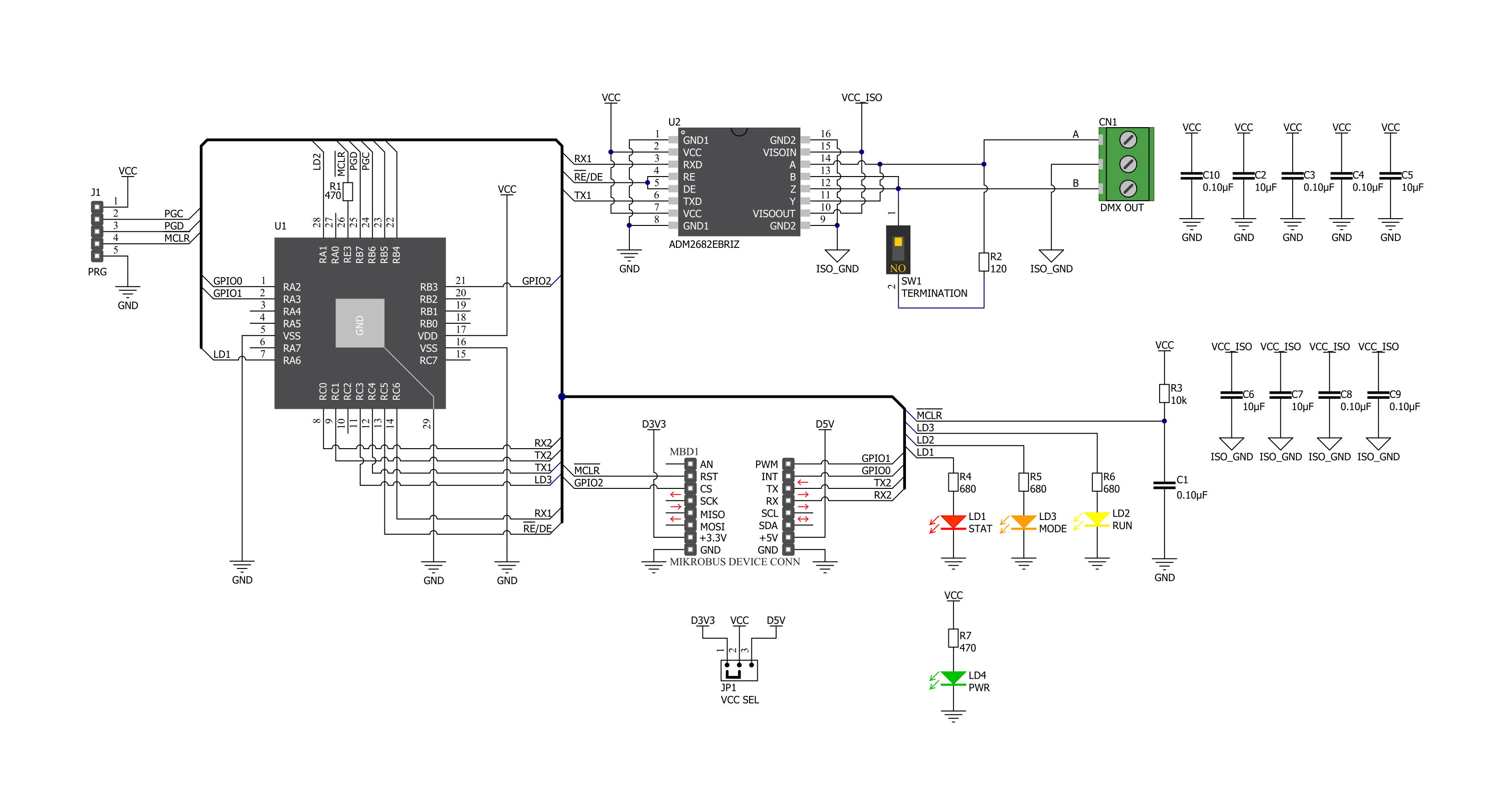
DMX Click is based on two different ICs: the first one is the PIC18F26K42 from Microchip, which is, among other peripherals, equipped with a DMX512 (DMX) hardware module. This makes it a very robust alternative to many similar software-based solutions, which generate all the specific DMX timings by dynamically switching the UART baud rate, or by using some similar techniques. The second IC is the ADM2862E from Analog Devices, a very compact and robust RS485 transceiver, which provides up to 5kV of galvanic isolation between the bus and the controller side. The same IC was used in RS485 2 Click where you can find a brief explanation of its functionalities. More detailed information can be found in its official datasheet, in the links below. The basic concept of DMX Click is to take plain UART data at any baud rate at its input and use it to fill in the channel data of any of the 512 available DMX slots, without worrying about timings, signal conversion, frame rates, etc. In other words, DMX Click supports controlling a single DMX Universe over the common UART interface found on almost every MCU, which opens up many design possibilities. It can be used to design an independent control desk (DMX MASTER), which doesn't require a PC to be connected. It can also be used to design custom DMX SLAVE applications very easily. The DMX protocol itself has some specifics, which need to
be explained in order to better understand how the Click board™ works: the DMX data format is very similar to a common UART, except it is fixed to a data rate of 250kbps, one start bit, eight data bits, two stop bits and no parity. Considering the fixed DMX baud rate, it takes approximately 23ms to send 513 bytes of data, along with BR and MAB signals, which translates to a maximum frame rate of 44 Hz. In other words, the channel data of a single slot can be updated 44 times per second. If higher frame rates are required (e.g. smoother movement, smoother light transition), the entire frame can be shortened. DMX512-A standard doesn't require sending all 512 slots, which can save time between two frames. DMX Click can be operated in both MASTER and SLAVE modes. It allows many of DMX parameters to be configured for each mode, by using simple UART commands interface. User can configure the frame length itself, gap length between two consecutive frames, number of channels within the frame, duration of the interrupt signal after each frame, and so on. The DMX Click Manual provides all the necessary information about the available parameters in both modes. The firmware on the PIC26K42 MCU utilizes two memory buffers. Incoming data from the UART input is stored in the first buffer (A), while the second buffer (B) is transferred to the UART output. Data transfer is performed
by using dedicated DMA channels. When the transfer is done and if the A buffer is full, the DMA transfer restarts, while the buffers are swapped. Now the buffer B is accepting data from the input, while the buffer A is transferred to the UART output. This is a typical double-buffering concept and it allows synchronization between two buffers working on different speeds. The input-side UART is configured to auto or fixed (115200) baud rate, while the output-side UART is set to a DMX mode and is routed to the RS485 transceiver. The 3-pole output terminal is used to connect the Click board™ to the DMX bus, with its connections clearly marked on the PCB (DN - Data Negative; DP - Data Positive; GND in the middle) The interrupt pin (INT) is used to signalize different events to the host MCU, while the STAT LED is used as a visual indication (i.e. for config errors). The MODE LED indicates operating mode (SLAVE or MASTER), while the RUN LED indicates the running status of the Click board™. Please refer to the DMX Click Manual for a detailed explanation of DMX Click functions in each mode. DMX Click offers a selection between 3.3V and 5V operation, with the onboard SMD jumper, labeled as PWR SEL. This allows both 3.3V and 5V MCUs to be interfaced with this Click board™.

Features overview
Development board
Curiosity PIC32 MZ EF development board is a fully integrated 32-bit development platform featuring the high-performance PIC32MZ EF Series (PIC32MZ2048EFM) that has a 2MB Flash, 512KB RAM, integrated FPU, Crypto accelerator, and excellent connectivity options. It includes an integrated programmer and debugger, requiring no additional hardware. Users can expand
functionality through MIKROE mikroBUS™ Click™ adapter boards, add Ethernet connectivity with the Microchip PHY daughter board, add WiFi connectivity capability using the Microchip expansions boards, and add audio input and output capability with Microchip audio daughter boards. These boards are fully integrated into PIC32’s powerful software framework, MPLAB Harmony,
which provides a flexible and modular interface to application development a rich set of inter-operable software stacks (TCP-IP, USB), and easy-to-use features. The Curiosity PIC32 MZ EF development board offers expansion capabilities making it an excellent choice for a rapid prototyping board in Connectivity, IOT, and general-purpose applications.

Microcontroller Overview
MCU Card / MCU

Architecture
PIC32
MCU Memory (KB)
2048
Silicon Vendor
Microchip
Pin count
100
RAM (Bytes)
524288
Used MCU Pins
mikroBUS™ mapper
Take a closer look
Click board™ Schematic
Step by step
Project assembly

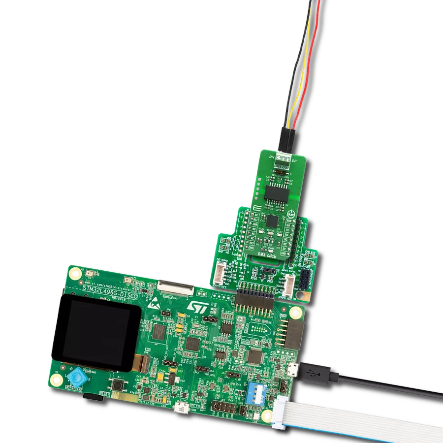
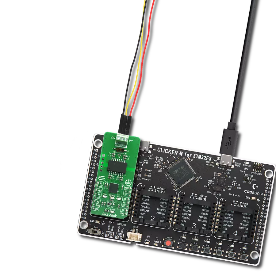
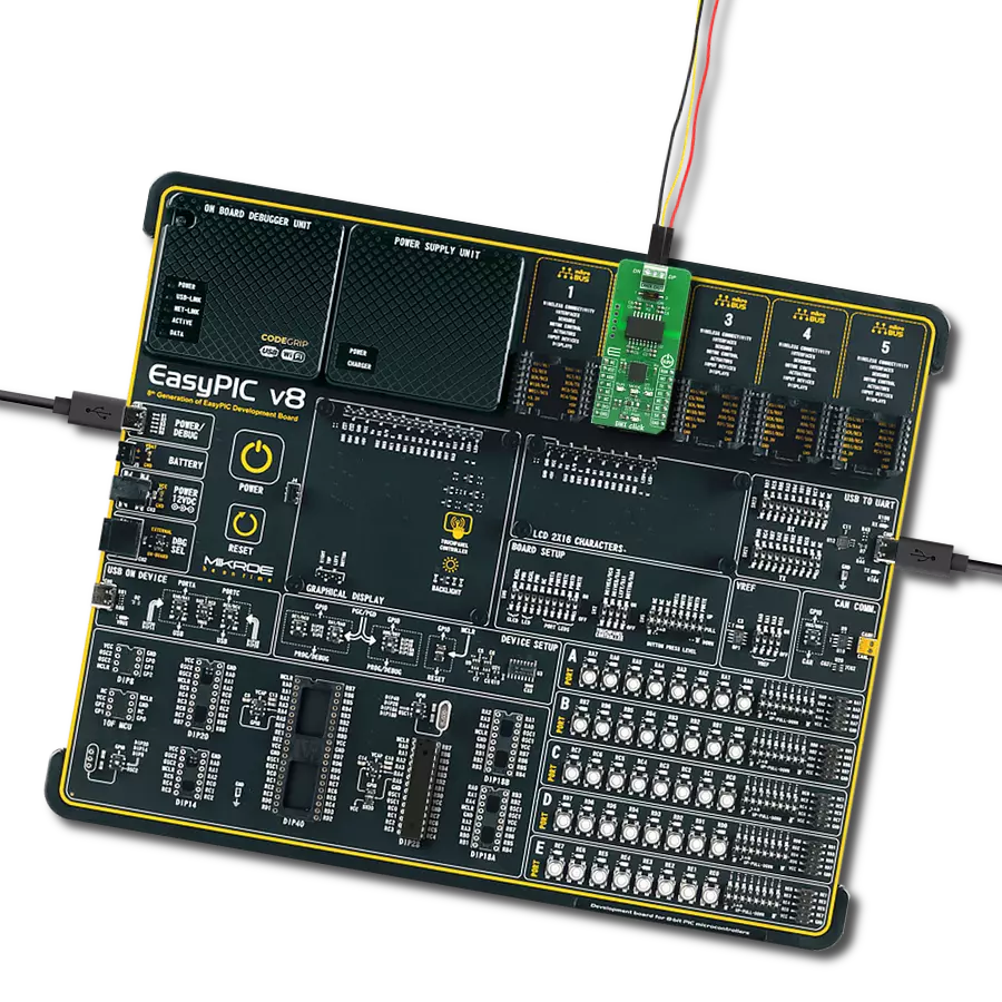
Start by selecting your development board and Click board™. Begin with the Curiosity PIC32 MZ EF as your development board.


Track your results in real time
Application Output
1. Application Output - In Debug mode, the 'Application Output' window enables real-time data monitoring, offering direct insight into execution results. Ensure proper data display by configuring the environment correctly using the provided tutorial.

2. UART Terminal - Use the UART Terminal to monitor data transmission via a USB to UART converter, allowing direct communication between the Click board™ and your development system. Configure the baud rate and other serial settings according to your project's requirements to ensure proper functionality. For step-by-step setup instructions, refer to the provided tutorial.

3. Plot Output - The Plot feature offers a powerful way to visualize real-time sensor data, enabling trend analysis, debugging, and comparison of multiple data points. To set it up correctly, follow the provided tutorial, which includes a step-by-step example of using the Plot feature to display Click board™ readings. To use the Plot feature in your code, use the function: plot(*insert_graph_name*, variable_name);. This is a general format, and it is up to the user to replace 'insert_graph_name' with the actual graph name and 'variable_name' with the parameter to be displayed.

Software Support
Library Description
This library contains API for DMX Click driver.
Key functions:
dmx_generic_write- Generic write function.dmx_generic_read- Generic read function.dmx_send_cmd- Send command function.
Open Source
Code example
The complete application code and a ready-to-use project are available through the NECTO Studio Package Manager for direct installation in the NECTO Studio. The application code can also be found on the MIKROE GitHub account.
/*!
 * \file
 * \brief DMX Click example
 *
 * # Description
 * This example demonstrates the use of the DMX Click board by showcasing
 * the control for a 6-channel DMX RGB LED reflector connected to it.
 *
 * The demo application is composed of two sections :
 *
 * ## Application Init
 * Initializes the driver and performs the Click default configuration.
 *
 * ## Application Task
 * Performs the LEDs dimming control on a 6-channel DMX RGB LED reflector.
 *
 * \author MikroE Team
 *
 */
#include "board.h"
#include "log.h"
#include "dmx.h"
#include "string.h"

// Application buffer size
#define APP_BUFFER_SIZE         256
#define PROCESS_BUFFER_SIZE     256

/**
 * @brief Application example variables.
 * @details Variables used in application example.
 */
static uint8_t app_buf[ APP_BUFFER_SIZE ] = { 0 };
static int32_t app_buf_len = 0;
static dmx_t dmx;
static log_t logger;

/**
 * @brief Clearing application buffer.
 * @details This function clears memory of application
 * buffer and reset its length.
 */
static void dmx_clear_app_buf ( void );

/**
 * @brief Data reading function.
 * @details This function reads data from device and
 * appends it to the application buffer.
 * @return @li @c  0 - Some data is read.
 *         @li @c -1 - Nothing is read.
 * See #err_t definition for detailed explanation.
 */
static err_t dmx_process ( void );

/**
 * @brief Logs application buffer.
 * @details This function logs data from application buffer.
 */
static void dmx_log_app_buf ( void );

/**
 * @brief Response check.
 * @details This function checks for response and
 * returns the status of response.
 * @param[in] rsp  Expected response.
 * @return @li @c  0 - OK response.
 *         @li @c -1 - Unknown error.
 *         @li @c -2 - Timeout error.
 * See #err_t definition for detailed explanation.
 */
static err_t dmx_rsp_check ( uint8_t *rsp );

// ------------------------------------------------------ APPLICATION FUNCTIONS

void application_init ( void )
{
    log_cfg_t log_cfg;
    dmx_cfg_t cfg;

    /**
     * Logger initialization.
     * Default baud rate: 115200
     * Default log level: LOG_LEVEL_DEBUG
     * @note If USB_UART_RX and USB_UART_TX
     * are defined as HAL_PIN_NC, you will
     * need to define them manually for log to work.
     * See @b LOG_MAP_USB_UART macro definition for detailed explanation.
     */
    LOG_MAP_USB_UART( log_cfg );
    log_init( &logger, &log_cfg );
    log_info( &logger, " Application Init " );

    // Click initialization.
    dmx_cfg_setup( &cfg );
    DMX_MAP_MIKROBUS( cfg, MIKROBUS_1 );
    dmx_init( &dmx, &cfg );

    dmx_set_auto_baud_rate( &dmx, 1 );
    Delay_ms ( 100 );

    dmx_reset( &dmx, DMX_MASTER );
    dmx_run( &dmx, DMX_CONFIG_MODE );
    Delay_ms ( 100 );

    dmx_process( );
    dmx_clear_app_buf( );

    // Clear the internal buffers
    dmx_send_cmd( &dmx, DMX_CMD_PURGEBFR );
    dmx_rsp_check( DMX_RSP_OK );
    dmx_log_app_buf( );

    // Set start address
    dmx_send_cmd( &dmx, DMX_CMD_SADR );
    dmx_rsp_check( DMX_RSP_OK );
    dmx_log_app_buf( );

    // Set input data buffer length
    dmx_send_cmd( &dmx, DMX_CMD_BLEN );
    dmx_rsp_check( DMX_RSP_OK );
    dmx_log_app_buf( );

    // Set DMX frame length
    dmx_send_cmd( &dmx, DMX_CMD_FLEN_MASTER );
    dmx_rsp_check( DMX_RSP_OK );
    dmx_log_app_buf( );

    // Set interrupt pulse duration
    dmx_send_cmd( &dmx, DMX_CMD_ITMR );
    dmx_rsp_check( DMX_RSP_OK );
    dmx_log_app_buf( );

    // Set a time delay between two frames
    dmx_send_cmd( &dmx, DMX_CMD_FTMR );
    dmx_rsp_check( DMX_RSP_OK );
    dmx_log_app_buf( );

    // Display configuration
    dmx_send_cmd( &dmx, DMX_CMD_DISPLCFG );
    dmx_rsp_check( DMX_RSP_OK );
    dmx_log_app_buf( );
    dmx_clear_app_buf( );

    dmx_run( &dmx, DMX_RUN_MODE );

    log_info( &logger, " Application Task " );
    Delay_ms ( 500 );
}

void application_task ( void )
{
    uint8_t dmx_6_ch_buf[ 6 ] = { 0 };
    int16_t cnt = 0;

    dmx_6_ch_buf[ 0 ] = 255; // Dimmer
    dmx_6_ch_buf[ 1 ] = 0;   // Red
    dmx_6_ch_buf[ 2 ] = 0;   // Green
    dmx_6_ch_buf[ 3 ] = 0;   // Blue
    dmx_6_ch_buf[ 4 ] = 0;   // Strobe
    dmx_6_ch_buf[ 5 ] = 0;   // Macro

    log_printf( &logger, "\r\nDimming RED LEDs\r\n" );
    for ( cnt = 0; cnt <= 255; cnt++ )
    {
        dmx_6_ch_buf[ 1 ] = cnt;
        dmx_generic_write( &dmx, dmx_6_ch_buf, 6 );
        Delay_ms ( 1 );
    }
    for ( cnt = 255; cnt >= 0; cnt-- )
    {
        dmx_6_ch_buf[ 1 ] = cnt;
        dmx_generic_write( &dmx, dmx_6_ch_buf, 6 );
        Delay_ms ( 1 );
    }

    log_printf( &logger, "Dimming GREEN LEDs\r\n" );
    for ( cnt = 0; cnt <= 255; cnt++ )
    {
        dmx_6_ch_buf[ 2 ] = cnt;
        dmx_generic_write( &dmx, dmx_6_ch_buf, 6 );
        Delay_ms ( 1 );
    }
    for ( cnt = 255; cnt >= 0; cnt-- )
    {
        dmx_6_ch_buf[ 2 ] = cnt;
        dmx_generic_write( &dmx, dmx_6_ch_buf, 6 );
        Delay_ms ( 1 );
    }

    log_printf( &logger, "Dimming BLUE LEDs\r\n" );
    for ( cnt = 0; cnt <= 255; cnt++ )
    {
        dmx_6_ch_buf[ 3 ] = cnt;
        dmx_generic_write( &dmx, dmx_6_ch_buf, 6 );
        Delay_ms ( 1 );
    }
    for ( cnt = 255; cnt >= 0; cnt-- )
    {
        dmx_6_ch_buf[ 3 ] = cnt;
        dmx_generic_write( &dmx, dmx_6_ch_buf, 6 );
        Delay_ms ( 1 );
    }

    dmx_6_ch_buf[ 1 ] = 255;
    dmx_6_ch_buf[ 2 ] = 255;
    dmx_6_ch_buf[ 3 ] = 255;
    log_printf( &logger, "Dimming all LEDs\r\n" );
    for ( cnt = 0; cnt <= 255; cnt++ )
    {
        dmx_6_ch_buf[ 0 ] = cnt;
        dmx_generic_write( &dmx, dmx_6_ch_buf, 6 );
        Delay_ms ( 1 );
    }
    for ( cnt = 255; cnt >= 0; cnt-- )
    {
        dmx_6_ch_buf[ 0 ] = cnt;
        dmx_generic_write( &dmx, dmx_6_ch_buf, 6 );
        Delay_ms ( 1 );
    }
}

int main ( void )
{
    /* Do not remove this line or clock might not be set correctly. */
    #ifdef PREINIT_SUPPORTED
    preinit();
    #endif

    application_init( );

    for ( ; ; )
    {
        application_task( );
    }

    return 0;
}

static void dmx_clear_app_buf ( void )
{
    memset( app_buf, 0, app_buf_len );
    app_buf_len = 0;
}

static err_t dmx_process ( void )
{
    uint8_t rx_buf[ PROCESS_BUFFER_SIZE ] = { 0 };
    int32_t rx_size = 0;
    rx_size = dmx_generic_read( &dmx, rx_buf, PROCESS_BUFFER_SIZE );
    if ( rx_size > 0 )
    {
        int32_t buf_cnt = app_buf_len;
        if ( ( ( app_buf_len + rx_size ) > APP_BUFFER_SIZE ) && ( app_buf_len > 0 ) )
        {
            buf_cnt = APP_BUFFER_SIZE - ( ( app_buf_len + rx_size ) - APP_BUFFER_SIZE );
            memmove ( app_buf, &app_buf[ APP_BUFFER_SIZE - buf_cnt ], buf_cnt );
        }
        for ( int32_t rx_cnt = 0; rx_cnt < rx_size; rx_cnt++ )
        {
            if ( rx_buf[ rx_cnt ] )
            {
                app_buf[ buf_cnt++ ] = rx_buf[ rx_cnt ];
                if ( app_buf_len < APP_BUFFER_SIZE )
                {
                    app_buf_len++;
                }
            }
        }
        return DMX_OK;
    }
    return DMX_ERROR;
}

static void dmx_log_app_buf ( void )
{
    for ( int32_t buf_cnt = 0; buf_cnt < app_buf_len; buf_cnt++ )
    {
        log_printf( &logger, "%c", app_buf[ buf_cnt ] );
    }
}

static err_t dmx_rsp_check ( uint8_t *rsp )
{
    uint32_t timeout_cnt = 0;
    uint32_t timeout = 60000;
    dmx_clear_app_buf( );
    dmx_process( );
    while ( ( 0 == strstr( app_buf, rsp ) ) &&
            ( 0 == strstr( app_buf, DMX_RSP_ERROR ) ) )
    {
        dmx_process( );
        if ( timeout_cnt++ > timeout )
        {
            dmx_clear_app_buf( );
            return DMX_ERROR_TIMEOUT;
        }
        Delay_ms ( 1 );
    }
    Delay_ms ( 100 );
    dmx_process( );
    if ( strstr( app_buf, rsp ) )
    {
        return DMX_OK;
    }
    return DMX_ERROR;
}

// ------------------------------------------------------------------------ END