Create a a reliable platform for encoding, decoding, and transmitting telephonic signals with CMX865A and PIC32MZ2048EFM100
Send alerts or receive commands over the phone line
Published Mar 11, 2024
Click board™
DTMF Click
Dev. board
Curiosity PIC32 MZ EF
Compiler
NECTO Studio
MCU
PIC32MZ2048EFM100
Enhance your projects with crystal-clear voice and data communications, easily managed through advanced DTMF signal processing technology
A
A
Hardware Overview
How does it work?
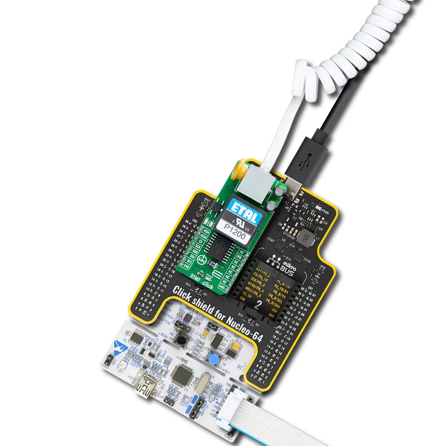
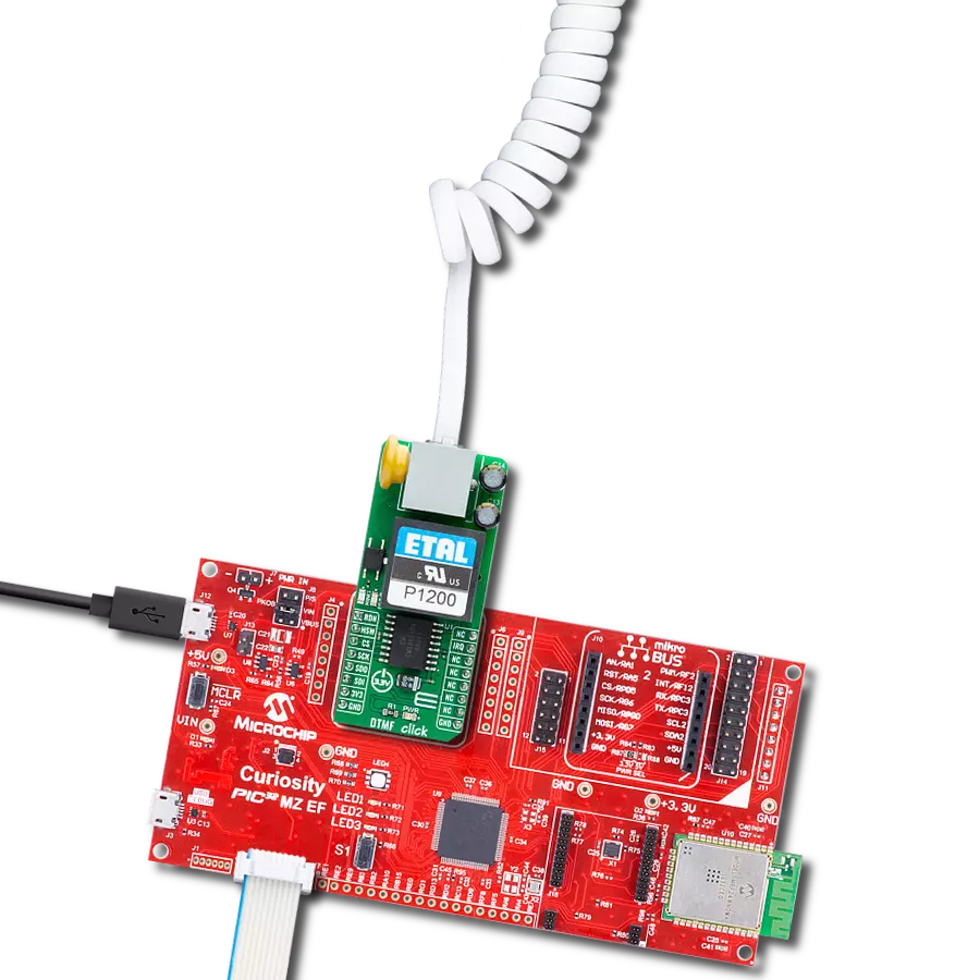
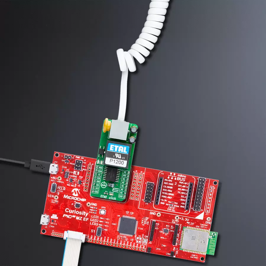
DTMF Click is based on the CMX865A, a high-performance DTMF Codec/FSK Combo multi-standard modem from CML Micro. This Click board™ stands out for its integration of both an industrial standard DTMF encoder/decoder and a versatile FSK modem, catering to a variety of telephone connectivity and interconnect applications. The CMX865A's ability to handle basic call setups and progress functionalities, coupled with its capacity for data signaling, makes it suitable for remote control, status notification, and data acquisition across numerous fields. As mentioned, the CMX865A combines a high-quality DTMF decoder known for its resistance to voice falsing and a multifaceted FSK modem that supports standards like V.23, V.21, Bell 103, and Bell 202. Users benefit from its dual operational
modes, which are programmable for transmission and reception, allowing for the transmission of programmed signals, simple melodies, or modem tones. Its applicability extends to security systems that rely on DTMF for access control, automated response services for customer interaction, and IoT devices requiring remote control over telephony networks. Additionally, its on-chip line driver, hybrid, and receiver circuits, complemented by external components and a P1200 transformer, offer a complete, fully isolated line interface solution. Data and control exchanges between the CMX865A and the host MCU are made through a C-BUS interface, compatible with a standard 4-wire SPI interface of the mikroBUS™ socket. The board also uses the mikroBUS™ socket's RDN pin and a red RING LED to indicate ringing signals and the
IRQ pin for interrupt requests related to call states like busy, dialing, and connected statuses. The HSW pin, alongside a blue HOOK LED, also serves as a hookswitch to manage the line interface's connectivity status (0-OFF, 1-ON). An additional feature of the CMX865A is the Powersave mode, which conserves energy by deactivating all circuits except the essential C-BUS (SPI) interface. This Click board™ can be operated only with a 3.3V logic voltage level. The board must perform appropriate logic voltage level conversion before using MCUs with different logic levels. Also, it comes equipped with a library containing functions and an example code that can be used as a reference for further development.

Features overview
Development board
Curiosity PIC32 MZ EF development board is a fully integrated 32-bit development platform featuring the high-performance PIC32MZ EF Series (PIC32MZ2048EFM) that has a 2MB Flash, 512KB RAM, integrated FPU, Crypto accelerator, and excellent connectivity options. It includes an integrated programmer and debugger, requiring no additional hardware. Users can expand
functionality through MIKROE mikroBUS™ Click™ adapter boards, add Ethernet connectivity with the Microchip PHY daughter board, add WiFi connectivity capability using the Microchip expansions boards, and add audio input and output capability with Microchip audio daughter boards. These boards are fully integrated into PIC32’s powerful software framework, MPLAB Harmony,
which provides a flexible and modular interface to application development a rich set of inter-operable software stacks (TCP-IP, USB), and easy-to-use features. The Curiosity PIC32 MZ EF development board offers expansion capabilities making it an excellent choice for a rapid prototyping board in Connectivity, IOT, and general-purpose applications.

Microcontroller Overview
MCU Card / MCU

Architecture
PIC32
MCU Memory (KB)
2048
Silicon Vendor
Microchip
Pin count
100
RAM (Bytes)
524288
Used MCU Pins
mikroBUS™ mapper
Take a closer look
Click board™ Schematic

Step by step
Project assembly

Start by selecting your development board and Click board™. Begin with the Curiosity PIC32 MZ EF as your development board.


Software Support
Library Description
This library contains API for DTMF Click driver.
Key functions:
dtmf_handshake_init- This function performs a handshake init which resets the device settings to defaultdtmf_dial- This function dials the selected number by alternating between DTMF and No-tonedtmf_send_message- This function sends an array of bytes via V.23 FSK 1200bps modem in start-stop 8.1 mode
Open Source
Code example
The complete application code and a ready-to-use project are available through the NECTO Studio Package Manager for direct installation in the NECTO Studio. The application code can also be found on the MIKROE GitHub account.
/*!
 * @file main.c
 * @brief DTMF Click example
 *
 * # Description
 * This example demonstrates the use of DTMF Click board by showing
 * the communication between the two Click boards connected to PBX system.
 *
 * The demo application is composed of two sections :
 *
 * ## Application Init
 * Initializes the driver and logger, and displays the selected application mode.
 *
 * ## Application Task
 * Dialing application mode:
 * - Resets the device settings and dials the selected number. If a call is answered
 * it starts sending desired messages every couple of seconds with constantly checking
 * if a call is still in progress or it's terminated from the other side.
 * Answering application mode:
 * - Resets the device settings and waits for an incoming call indication, answers the call,
 * and waits for a desired number of messages. The call is terminated after all messages
 * are received successfully.
 *
 * @note
 * We have used a Yeastar S20 VoIP PBX system for the test, where the Click boards are
 * connected to ports 1 and 2 configured as FXS extension with numbers 1000 and 1001 (dialer).
 *
 * @author Stefan Filipovic
 *
 */

#include "board.h"
#include "log.h"
#include "dtmf.h"

// Demo aplication selection macros
#define APP_DIALING                 0
#define APP_ANSWERING               1
#define DEMO_APP                    APP_DIALING

// Dialing application settings - a dial number and text to send (must end with CRLF - \r\n)
#define DIAL_NUMBER                 "1000"
#define TEXT_TO_SEND                "MIKROE - DTMF Click\r\n"

// Answering application settings - a number of successfully received messages before call termination
#define NUM_MESSAGES                5u

static dtmf_t dtmf;
static log_t logger;

void application_init ( void )
{
    log_cfg_t log_cfg;  /**< Logger config object. */
    dtmf_cfg_t dtmf_cfg;  /**< Click config object. */

    /**
     * Logger initialization.
     * Default baud rate: 115200
     * Default log level: LOG_LEVEL_DEBUG
     * @note If USB_UART_RX and USB_UART_TX
     * are defined as HAL_PIN_NC, you will
     * need to define them manually for log to work.
     * See @b LOG_MAP_USB_UART macro definition for detailed explanation.
     */
    LOG_MAP_USB_UART( log_cfg );
    log_init( &logger, &log_cfg );
    log_info( &logger, " Application Init " );

    // Click initialization.
    dtmf_cfg_setup( &dtmf_cfg );
    DTMF_MAP_MIKROBUS( dtmf_cfg, MIKROBUS_1 );
    if ( SPI_MASTER_ERROR == dtmf_init( &dtmf, &dtmf_cfg ) )
    {
        log_error( &logger, " Communication init." );
        for ( ; ; );
    }

#if ( DEMO_APP == APP_DIALING )
    log_printf( &logger, " Application Mode: Dialing\r\n" );
#elif ( DEMO_APP == APP_ANSWERING )
    log_printf( &logger, " Application Mode: Answering\r\n" );
#else
    #error "Selected application mode is not supported!"
#endif

    log_info( &logger, " Application Task " );
}

void application_task ( void )
{
    uint8_t state = DTMF_STATE_IDLE;
    uint32_t time_cnt = 0;
    uint8_t msg_cnt = 0;

    dtmf_handshake_init ( &dtmf );

#if ( DEMO_APP == APP_DIALING )
    log_printf( &logger, "\r\n Hook OFF\r\n" );
    dtmf_hook_off ( &dtmf );
    Delay_ms ( 1000 );
    Delay_ms ( 1000 );
    Delay_ms ( 1000 );
    Delay_ms ( 1000 );
    log_printf( &logger, " Dial: %s\r\n", ( char * ) DIAL_NUMBER );
    dtmf_dial ( &dtmf, DIAL_NUMBER );
    dtmf.rx_mode &= DTMF_RX_LEVEL_MASK; // No change in rx level setting
    dtmf.rx_mode |= ( DTMF_RX_MODE_DTMF_TONES | DTMF_RX_TONE_DETECT_CALL_PROG );
    dtmf_set_receive_mode ( &dtmf, dtmf.rx_mode );
    for ( ; ; )
    {
        Delay_ms ( 1 );
        if ( !dtmf_get_irq_pin ( &dtmf ) )
        {
            time_cnt = 0;
            state = DTMF_STATE_IRQ_SET;
        }
        if ( ( DTMF_STATE_IRQ_SET == state ) && !dtmf_call_progress ( &dtmf ) )
        {
            if ( time_cnt < DTMF_TIMING_BUSY )
            {
                log_printf( &logger, " Busy\r\n" );
                break;
            }
            else if ( time_cnt < DTMF_TIMING_DISCONNECTED )
            {
                log_printf( &logger, " Disconnected\r\n" );
                break;
            }
            else if ( time_cnt < DTMF_TIMING_RINGING )
            {
                log_printf( &logger, " Ringing\r\n" );
                state = DTMF_STATE_RINGING;
            }
        }
        if ( ( DTMF_STATE_RINGING == state ) && ( time_cnt > DTMF_TIMING_CALL_PROGRESS ) )
        {
            log_printf( &logger, " Call in progress\r\n" );
            state = DTMF_STATE_CALL_IN_PROGRESS;
            time_cnt = 0;
        }
        if ( ( DTMF_STATE_CALL_IN_PROGRESS == state ) && !( time_cnt % DTMF_TIMING_SEND_MESSAGE ) )
        {
            log_printf( &logger, " Send message %u\r\n", ( uint16_t ) msg_cnt++ );
            dtmf_send_message ( &dtmf, TEXT_TO_SEND, strlen ( TEXT_TO_SEND ) );
        }
        if ( time_cnt++ > DTMF_TIMEOUT_CALL_PROGRESS )
        {
            log_printf( &logger, " Timeout\r\n" );
            break;
        }
    }
    log_printf( &logger, " Hook ON\r\n" );
    dtmf_hook_on ( &dtmf );
    Delay_ms ( 1000 );
    Delay_ms ( 1000 );
    Delay_ms ( 1000 );
    Delay_ms ( 1000 );
#elif ( DEMO_APP == APP_ANSWERING )
    uint8_t rx_data = 0;
    uint8_t msg_end_buff[ 2 ] = { 0 };

    log_printf( &logger, "\r\n Waiting for a call...\r\n" );

    while ( dtmf_get_rdn_pin ( &dtmf ) );

    Delay_ms ( 1000 );
    log_printf( &logger, " Hook OFF\r\n" );
    dtmf_hook_off ( &dtmf );
    Delay_ms ( 1000 );
    log_printf( &logger, " Waiting for %u messages...\r\n", ( uint16_t ) NUM_MESSAGES );
    dtmf.rx_mode &= DTMF_RX_LEVEL_MASK; // No change in rx level setting
    dtmf.rx_mode |= ( DTMF_RX_MODE_V23_FSK_1200 | DTMF_RX_USART_START_STOP | DTMF_RX_DATA_PARITY_8_NO_PAR );
    dtmf_set_receive_mode ( &dtmf, dtmf.rx_mode );

    for ( ; ; )
    {
        Delay_ms ( 1 );
        if ( !dtmf_get_irq_pin ( &dtmf ) )
        {
            if ( DTMF_STATE_IDLE != state )
            {
                log_printf( &logger, "\r\n Disconnected\r\n" );
                break;
            }
            log_printf( &logger, " Message %u: ", ( uint16_t ) msg_cnt );
            state = DTMF_STATE_IRQ_SET;
            time_cnt = 0;
        }
        if ( ( DTMF_STATE_IRQ_SET == state ) && !( time_cnt % DTMF_TIMING_RX_READY ) )
        {
            if ( dtmf_unscram_1s_det ( &dtmf ) && dtmf_rx_ready ( &dtmf ) )
            {
                dtmf_receive_data ( &dtmf, &rx_data );
                log_printf( &logger, "%c", ( uint16_t ) rx_data );
                if ( '\r' == rx_data )
                {
                    msg_end_buff[ 0 ] = rx_data;
                }
                else if ( '\n' == rx_data )
                {
                    msg_end_buff[ 1 ] = rx_data;
                }
                else
                {
                    msg_end_buff[ 0 ] = 0;
                    msg_end_buff[ 1 ] = 0;
                }
            }
            if ( ( '\r' == msg_end_buff[ 0 ] ) && ( '\n' == msg_end_buff[ 1 ] ) )
            {
                msg_end_buff[ 0 ] = 0;
                msg_end_buff[ 1 ] = 0;
                state = DTMF_STATE_IDLE;
                if ( NUM_MESSAGES == ++msg_cnt )
                {
                    Delay_ms ( 100 );
                    log_printf( &logger, " Terminate call\r\n" );
                    Delay_ms ( 100 );
                    break;
                }
            }
        }
        if ( time_cnt++ > DTMF_TIMING_WAIT_FOR_MESSAGE )
        {
            log_printf( &logger, "\r\n Timeout\r\n" );
            break;
        }
    }
    log_printf( &logger, " Hook ON\r\n" );
    dtmf_hook_on ( &dtmf );
    Delay_ms ( 1000 );
    Delay_ms ( 1000 );
    Delay_ms ( 1000 );
    Delay_ms ( 1000 );
#endif
}

int main ( void )
{
    /* Do not remove this line or clock might not be set correctly. */
    #ifdef PREINIT_SUPPORTED
    preinit();
    #endif

    application_init( );

    for ( ; ; )
    {
        application_task( );
    }

    return 0;
}

// ------------------------------------------------------------------------ END
Additional Support
Resources
Category:Signal Processing