Deliver high-quality visuals for your embedded projects with the ER-TFT1.54-2 and PIC32MZ2048EFM100
High-resolution 1.54" TFT LCD display solution with 240x240px resolution for sharp and detailed images

Published Dec 09, 2024
Click board™
IPS Display 2 Click
Dev. board
Curiosity PIC32 MZ EF
Compiler
NECTO Studio
MCU
PIC32MZ2048EFM100
Bring vibrant, high-resolution graphics to your embedded projects with a compact 1.54" TFT display
A
A
Hardware Overview
How does it work?
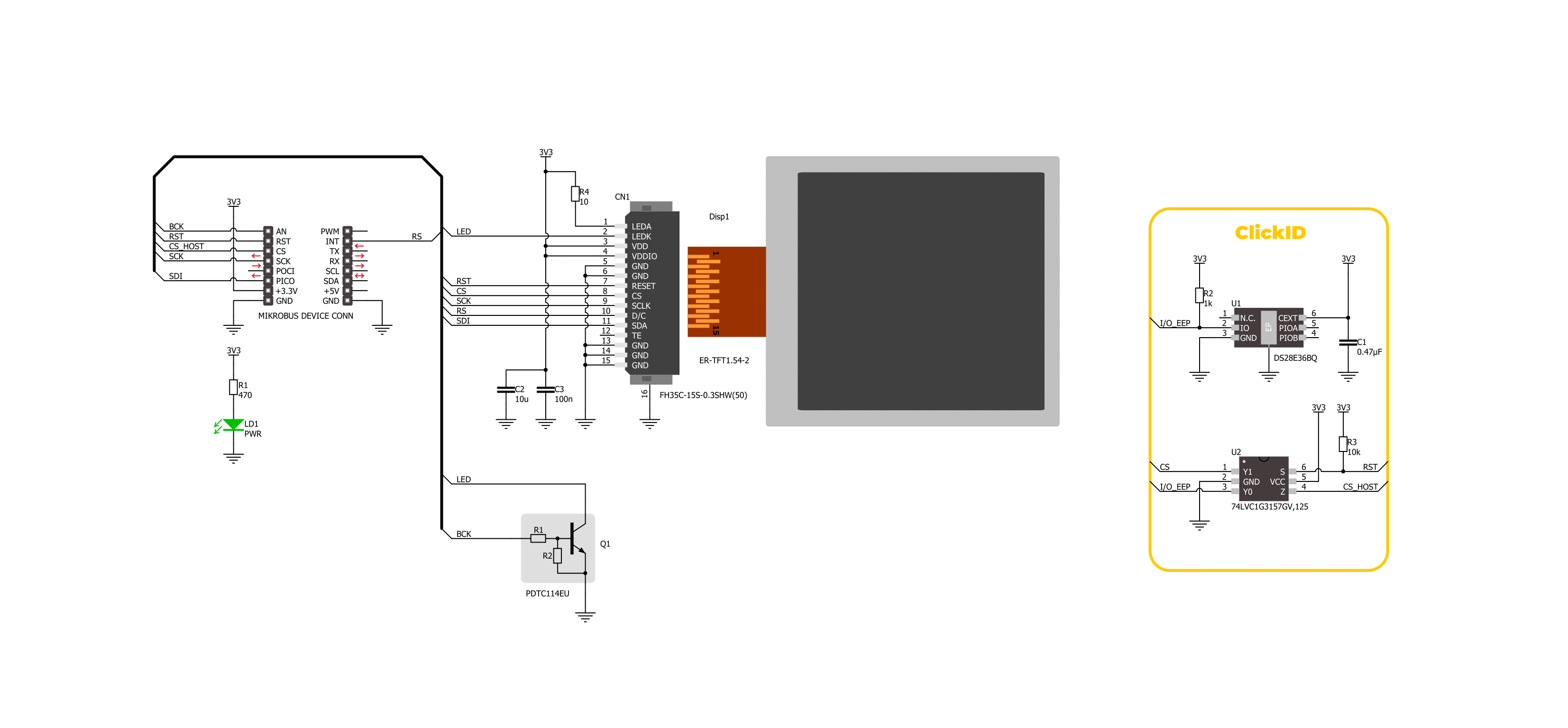
IPS Display 2 Click is based on the ER-TFT1.54-2, a 1.54" TFT LCD display without a touch panel from BuyDisplay, a division of EastRising Technology. Designed for high-resolution visual output, this display offers a crisp 240x240 pixel resolution, ideal for applications requiring clear and vibrant graphics. It connects through an 15-pin FPC connector with a 0.3mm pitch, ensuring stable communication with the host system. This board is suitable for projects requiring a compact, high-resolution screen, such as handheld devices, smart displays, or informational panels. Though the display is not sunlight-readable, its compact design integrates it into various indoor applications. With a diagonal size of 1.54 inches, it boasts a compact form factor, featuring an outline dimension of 31.52mm (W) by 313.72mm (H) with the FPC
folded and a thickness of just 1.9mm. The visual area of 28.72mm by 28.72mm ensures an optimal display experience, while the active area of 27.72mm (W) by 27.72mm (H) provides high precision in rendering content. The dot pitch of 0.1155mm by 0.1155mm guarantees fine detail in the display's output. The ER-TFT1.54-2 is driven by the ST7789V controller, a highly integrated single-chip controller and driver specifically designed for 262K-color graphic TFT-LCDs, offering vibrant color depth and smooth graphical performance. This board operates through a 3-wire serial SPI interface, ensuring smooth communication between the display and the host MCU. Beyond the SPI interface pins, the display also uses additional control signals for enhanced functionality. The RST pin plays a crucial role in ensuring reliable
operation by allowing the display to be reset. This is essential for recovering from errors and initializing the display during power cycles. The BCK pin serves as a display backlight control, and the RS pin serves as a display data/command selection pin, crucial for distinguishing between data and command instructions sent via the SPI interface. This enables precise control over the display's functionality, ensuring that graphical content and operational commands are processed correctly. This Click board™ can be operated only with a 3.3V logic voltage level. The board must perform appropriate logic voltage level conversion before using MCUs with different logic levels. Also, it comes equipped with a library containing functions and an example code that can be used as a reference for further development.

Features overview
Development board
Curiosity PIC32 MZ EF development board is a fully integrated 32-bit development platform featuring the high-performance PIC32MZ EF Series (PIC32MZ2048EFM) that has a 2MB Flash, 512KB RAM, integrated FPU, Crypto accelerator, and excellent connectivity options. It includes an integrated programmer and debugger, requiring no additional hardware. Users can expand
functionality through MIKROE mikroBUS™ Click™ adapter boards, add Ethernet connectivity with the Microchip PHY daughter board, add WiFi connectivity capability using the Microchip expansions boards, and add audio input and output capability with Microchip audio daughter boards. These boards are fully integrated into PIC32’s powerful software framework, MPLAB Harmony,
which provides a flexible and modular interface to application development a rich set of inter-operable software stacks (TCP-IP, USB), and easy-to-use features. The Curiosity PIC32 MZ EF development board offers expansion capabilities making it an excellent choice for a rapid prototyping board in Connectivity, IOT, and general-purpose applications.

Microcontroller Overview
MCU Card / MCU

Architecture
PIC32
MCU Memory (KB)
2048
Silicon Vendor
Microchip
Pin count
100
RAM (Bytes)
524288
Used MCU Pins
mikroBUS™ mapper
Take a closer look
Click board™ Schematic
Step by step
Project assembly

Start by selecting your development board and Click board™. Begin with the Curiosity PIC32 MZ EF as your development board.


Track your results in real time
Application Output
1. Application Output - In Debug mode, the 'Application Output' window enables real-time data monitoring, offering direct insight into execution results. Ensure proper data display by configuring the environment correctly using the provided tutorial.

2. UART Terminal - Use the UART Terminal to monitor data transmission via a USB to UART converter, allowing direct communication between the Click board™ and your development system. Configure the baud rate and other serial settings according to your project's requirements to ensure proper functionality. For step-by-step setup instructions, refer to the provided tutorial.

3. Plot Output - The Plot feature offers a powerful way to visualize real-time sensor data, enabling trend analysis, debugging, and comparison of multiple data points. To set it up correctly, follow the provided tutorial, which includes a step-by-step example of using the Plot feature to display Click board™ readings. To use the Plot feature in your code, use the function: plot(*insert_graph_name*, variable_name);. This is a general format, and it is up to the user to replace 'insert_graph_name' with the actual graph name and 'variable_name' with the parameter to be displayed.

Software Support
Library Description
This library contains API for IPS Display 2 Click driver.
Key functions:
ipsdisplay2_fill_screen- This function fills the screen with the selected color.ipsdisplay2_write_string- This function writes a text string starting from the selected position in a 6x12 font size with a specified color.ipsdisplay2_draw_line- This function draws a line with a specified color.
Open Source
Code example
The complete application code and a ready-to-use project are available through the NECTO Studio Package Manager for direct installation in the NECTO Studio. The application code can also be found on the MIKROE GitHub account.
/*!
 * @file main.c
 * @brief IPS Display 2 Click example
 *
 * # Description
 * This example demonstrates the use of the IPS Display 2 Click board by showing
 * a practical example of using the implemented functions.
 *
 * The demo application is composed of two sections :
 *
 * ## Application Init
 * Initializes the driver and performs the Click default configuration.
 *
 * ## Application Task
 * Showcases the text writing example as well as drawing pictures and objects,
 * and filling the whole screen with a desired color. All data is logged on the USB UART
 * where you can track the program flow.
 *
 * @author Stefan Filipovic
 *
 */

#include "board.h"
#include "log.h"
#include "ipsdisplay2.h"
#include "ipsdisplay2_resources.h"

static ipsdisplay2_t ipsdisplay2;
static log_t logger;

void application_init ( void )
{
    log_cfg_t log_cfg;  /**< Logger config object. */
    ipsdisplay2_cfg_t ipsdisplay2_cfg;  /**< Click config object. */

    /**
     * Logger initialization.
     * Default baud rate: 115200
     * Default log level: LOG_LEVEL_DEBUG
     * @note If USB_UART_RX and USB_UART_TX
     * are defined as HAL_PIN_NC, you will
     * need to define them manually for log to work.
     * See @b LOG_MAP_USB_UART macro definition for detailed explanation.
     */
    LOG_MAP_USB_UART( log_cfg );
    log_init( &logger, &log_cfg );
    log_info( &logger, " Application Init " );

    // Click initialization.
    ipsdisplay2_cfg_setup( &ipsdisplay2_cfg );
    IPSDISPLAY2_MAP_MIKROBUS( ipsdisplay2_cfg, MIKROBUS_1 );
    if ( SPI_MASTER_ERROR == ipsdisplay2_init( &ipsdisplay2, &ipsdisplay2_cfg ) )
    {
        log_error( &logger, " Communication init." );
        for ( ; ; );
    }

    if ( IPSDISPLAY2_ERROR == ipsdisplay2_default_cfg ( &ipsdisplay2 ) )
    {
        log_error( &logger, " Default configuration." );
        for ( ; ; );
    }

    log_info( &logger, " Application Task " );
}

void application_task ( void )
{
    ipsdisplay2_point_t start_pt, end_pt;

#if IPSDISPLAY2_RESOURCES_INCLUDE_IMG
    log_printf( &logger, " Drawing MIKROE logo example\r\n\n" );
    ipsdisplay2_draw_picture ( &ipsdisplay2, IPSDISPLAY2_ROTATION_VERTICAL_0, ipsdisplay2_img_mikroe );
    Delay_ms ( 1000 );
    Delay_ms ( 1000 );
    Delay_ms ( 1000 );
#endif
    log_printf( &logger, " Writing text example\r\n\n" );
    ipsdisplay2_fill_screen ( &ipsdisplay2, IPSDISPLAY2_COLOR_BLACK );
    Delay_ms ( 1000 );
    start_pt.x = 0;
    start_pt.y = 50;
    ipsdisplay2_write_string ( &ipsdisplay2, start_pt, "      MIKROE      ", IPSDISPLAY2_COLOR_RED );
    start_pt.y += 20;
    ipsdisplay2_write_string ( &ipsdisplay2, start_pt, "   IPS Display 2  ", IPSDISPLAY2_COLOR_RED );
    start_pt.y += 20;
    ipsdisplay2_write_string ( &ipsdisplay2, start_pt, "       Click      ", IPSDISPLAY2_COLOR_RED );
    start_pt.y += 20;
    ipsdisplay2_write_string ( &ipsdisplay2, start_pt, "     240x240px    ", IPSDISPLAY2_COLOR_RED );
    start_pt.y += 20;
    ipsdisplay2_write_string ( &ipsdisplay2, start_pt, "ST7789V controller", IPSDISPLAY2_COLOR_RED );
    start_pt.y += 20;
    ipsdisplay2_write_string ( &ipsdisplay2, start_pt, "   TEST EXAMPLE   ", IPSDISPLAY2_COLOR_RED );
    Delay_ms ( 1000 );
    Delay_ms ( 1000 );
    Delay_ms ( 1000 );

    log_printf( &logger, " RGB fill screen example\r\n\n" );
    ipsdisplay2_fill_screen ( &ipsdisplay2, IPSDISPLAY2_COLOR_RED );
    Delay_ms ( 1000 );
    ipsdisplay2_fill_screen ( &ipsdisplay2, IPSDISPLAY2_COLOR_LIME );
    Delay_ms ( 1000 );
    ipsdisplay2_fill_screen ( &ipsdisplay2, IPSDISPLAY2_COLOR_BLUE );
    Delay_ms ( 1000 );

    log_printf( &logger, " Drawing objects example\r\n\n" );
    ipsdisplay2_fill_screen ( &ipsdisplay2, IPSDISPLAY2_COLOR_BLACK );
    Delay_ms ( 1000 );
    start_pt.x = IPSDISPLAY2_POS_WIDTH_MIN;
    start_pt.y = IPSDISPLAY2_POS_HEIGHT_MIN;
    end_pt.x = IPSDISPLAY2_POS_WIDTH_MAX;
    end_pt.y = IPSDISPLAY2_POS_HEIGHT_MAX;
    ipsdisplay2_draw_line ( &ipsdisplay2, start_pt, end_pt, IPSDISPLAY2_COLOR_BLUE );
    Delay_ms ( 1000 );
    start_pt.x = IPSDISPLAY2_POS_WIDTH_MAX;
    start_pt.y = IPSDISPLAY2_POS_HEIGHT_MIN;
    end_pt.x = IPSDISPLAY2_POS_WIDTH_MIN;
    end_pt.y = IPSDISPLAY2_POS_HEIGHT_MAX;
    ipsdisplay2_draw_line ( &ipsdisplay2, start_pt, end_pt, IPSDISPLAY2_COLOR_BLUE );
    Delay_ms ( 1000 );
    start_pt.x = 60;
    start_pt.y = 40;
    end_pt.x = 180;
    end_pt.y = 100;
    ipsdisplay2_draw_rectangle ( &ipsdisplay2, start_pt, end_pt, IPSDISPLAY2_COLOR_CYAN );
    Delay_ms ( 1000 );
    start_pt.y += 100;
    end_pt.y += 100;
    ipsdisplay2_draw_rectangle ( &ipsdisplay2, start_pt, end_pt, IPSDISPLAY2_COLOR_CYAN );
    Delay_ms ( 1000 );
    start_pt.x = 120;
    start_pt.y = 120;
    ipsdisplay2_draw_circle ( &ipsdisplay2, start_pt, start_pt.x, IPSDISPLAY2_COLOR_MAGENTA );
    Delay_ms ( 1000 );
    Delay_ms ( 1000 );
}

int main ( void )
{
    /* Do not remove this line or clock might not be set correctly. */
    #ifdef PREINIT_SUPPORTED
    preinit();
    #endif

    application_init( );

    for ( ; ; )
    {
        application_task( );
    }

    return 0;
}

// ------------------------------------------------------------------------ END