Revolutionize your data presentation with MCP23S17 and ATmega328P
See it in 2x16: Clear, Concise, Captivating!

Published Feb 14, 2024
Click board™
LCD mini Click
Dev. board
Arduino UNO Rev3
Compiler
NECTO Studio
MCU
ATmega328P
Elevate your solution's display capabilities, enhance the user experience, and unleash the full potential of an LCD display through seamless integration with an SPI adapter!
A
A
Hardware Overview
How does it work?
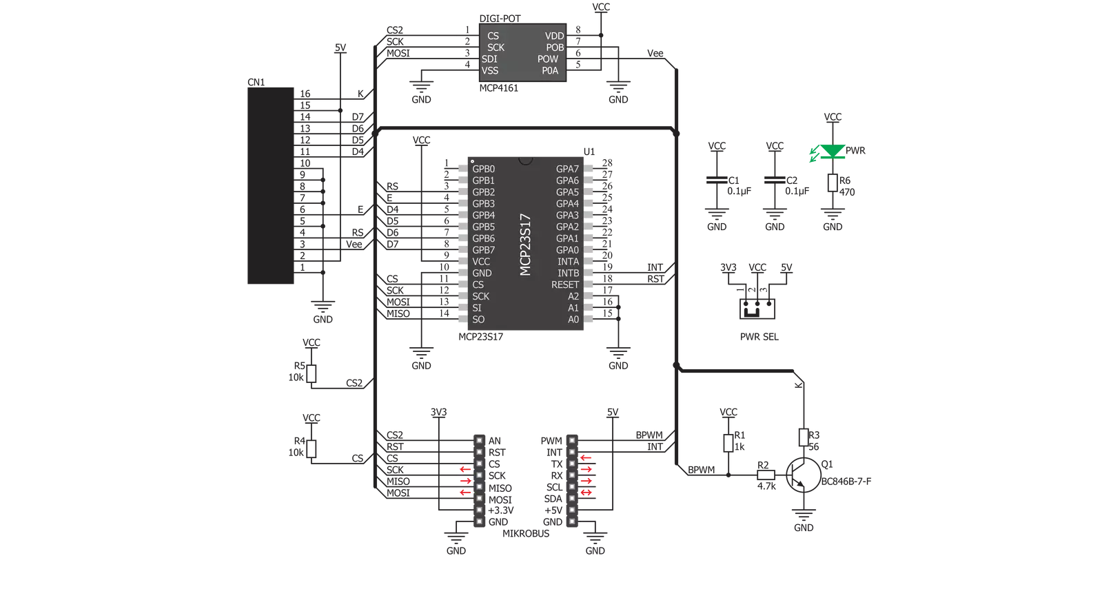
LCD Mini Click is based on the MCP23S17, a 16-bit I/O expander with a serial interface from Microchip. The MCP23S17 has an external reset input and a configurable interrupt source, which can also be configured as active-high or active-low. This bidirectional I2C expander acts as a bridge between the host MCU to four data bit pins, an enable control pin, and a register select pin of the display. In order to work, the enable pin should be held HIGH. The register-select pin toggles between command mode (logic LOW) and data mode (logic HIGH). The brightness of the backlight LED can be controlled directly over the
host MCU, but for the contrast of the LCD, there is the MCP4161, an 8-bit single SPI digital POT with non-volatile memory from Microchip. LCD Mini Click uses a standard 4-wire SPI serial interface from both the I2C expander and the digital potentiometer to communicate with the host MCU. The MCP23S17 supports a high-speed SPI interface of up to 10MHz and can be selected over the CS pin and reset over the RST pin. It sends interrupts over the INT pin. The MCP4161 also supports high-speed SPI of up to 10MHz and can be selected over the CS2 pin. The PWM pin can control the brightness of the LCD's backlight LED.
The LMB162XFW display with an appropriate cable does not come with the LCD Mini Click adapter board and is offered separately. However, the LCD Mini Click has an appropriate connector to interface the LCD. This Click board™ can operate with either 3.3V or 5V logic voltage levels selected via the PWR SEL jumper. This way, both 3.3V and 5V capable MCUs can use the communication lines properly. Also, this Click board™ comes equipped with a library containing easy-to-use functions and an example code that can be used as a reference for further development.


Features overview
Development board
Arduino UNO is a versatile microcontroller board built around the ATmega328P chip. It offers extensive connectivity options for various projects, featuring 14 digital input/output pins, six of which are PWM-capable, along with six analog inputs. Its core components include a 16MHz ceramic resonator, a USB connection, a power jack, an
ICSP header, and a reset button, providing everything necessary to power and program the board. The Uno is ready to go, whether connected to a computer via USB or powered by an AC-to-DC adapter or battery. As the first USB Arduino board, it serves as the benchmark for the Arduino platform, with "Uno" symbolizing its status as the
first in a series. This name choice, meaning "one" in Italian, commemorates the launch of Arduino Software (IDE) 1.0. Initially introduced alongside version 1.0 of the Arduino Software (IDE), the Uno has since become the foundational model for subsequent Arduino releases, embodying the platform's evolution.

Microcontroller Overview
MCU Card / MCU

Architecture
AVR
MCU Memory (KB)
32
Silicon Vendor
Microchip
Pin count
28
RAM (Bytes)
2048
You complete me!
Accessories
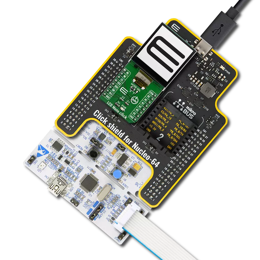
Click Shield for Arduino UNO has two proprietary mikroBUS™ sockets, allowing all the Click board™ devices to be interfaced with the Arduino UNO board without effort. The Arduino Uno, a microcontroller board based on the ATmega328P, provides an affordable and flexible way for users to try out new concepts and build prototypes with the ATmega328P microcontroller from various combinations of performance, power consumption, and features. The Arduino Uno has 14 digital input/output pins (of which six can be used as PWM outputs), six analog inputs, a 16 MHz ceramic resonator (CSTCE16M0V53-R0), a USB connection, a power jack, an ICSP header, and reset button. Most of the ATmega328P microcontroller pins are brought to the IO pins on the left and right edge of the board, which are then connected to two existing mikroBUS™ sockets. This Click Shield also has several switches that perform functions such as selecting the logic levels of analog signals on mikroBUS™ sockets and selecting logic voltage levels of the mikroBUS™ sockets themselves. Besides, the user is offered the possibility of using any Click board™ with the help of existing bidirectional level-shifting voltage translators, regardless of whether the Click board™ operates at a 3.3V or 5V logic voltage level. Once you connect the Arduino UNO board with our Click Shield for Arduino UNO, you can access hundreds of Click boards™, working with 3.3V or 5V logic voltage levels.

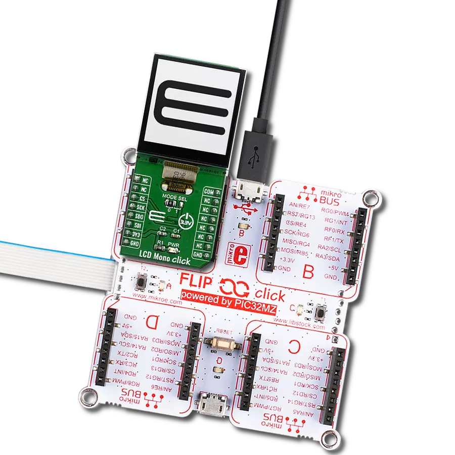
LCD mini display, based on the LMB162XFW, is a compact and versatile SPI-controlled LCD mini display featuring a sharp 2x16 pixel resolution. Its striking deep blue display color contrasts beautifully with the light yellow-green display data, ensuring clear and vibrant visuals. With a compact form factor, the display measures just 53.0x20.0x9.1mm (maximum dimensions), making it suitable for space-constrained applications. This mini display's SPI control enables seamless integration into various electronic projects, while its elegant color combination enhances visibility. Whether used in industrial instruments, consumer devices, or DIY electronics, the LCD mini display offers a sleek and functional solution for presenting essential data and information in a visually appealing manner.

Used MCU Pins
mikroBUS™ mapper
Take a closer look
Click board™ Schematic
Step by step
Project assembly

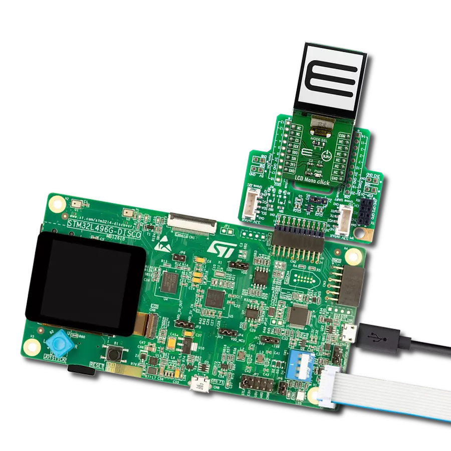
Start by selecting your development board and Click board™. Begin with the Arduino UNO Rev3 as your development board.


Software Support
Library Description
This library contains API for LCD mini Click driver.
Key functions:
lcdmini_set_backlight- Set backlight functionlcdmini_set_contrast- Set contrast functionlcdmini_display_text- LCD mini display text
Open Source
Code example
The complete application code and a ready-to-use project are available through the NECTO Studio Package Manager for direct installation in the NECTO Studio. The application code can also be found on the MIKROE GitHub account.
/*!
 * @file main.c
 * @brief LCDmini Click example
 *
 * # Description
 * This is an example that demonstrates the use of the LCD mini Click board.
 *
 * The demo application is composed of two sections :
 *
 * ## Application Init
 * Initialization driver enables - SPI, performing hardware reset, default config,
 * setting up the backlight, and entering text to be written.
 *
 * ## Application Task
 * This example shows the written text, then the text is moved left,
 * with changing between rows of the LCD screen.
 *
 * @note If the screen isn't initialized you may need to restart the device.
 *
 * @author Stefan Ilic
 *
 */

#include "board.h"
#include "log.h"
#include "lcdmini.h"

static lcdmini_t lcdmini;
static log_t logger;

void application_init ( void )
{
    log_cfg_t log_cfg;  /**< Logger config object. */
    lcdmini_cfg_t lcdmini_cfg;  /**< Click config object. */

    /**
     * Logger initialization.
     * Default baud rate: 115200
     * Default log level: LOG_LEVEL_DEBUG
     * @note If USB_UART_RX and USB_UART_TX
     * are defined as HAL_PIN_NC, you will
     * need to define them manually for log to work.
     * See @b LOG_MAP_USB_UART macro definition for detailed explanation.
     */
    LOG_MAP_USB_UART( log_cfg );
    log_init( &logger, &log_cfg );
    log_info( &logger, " Application Init " );

    // Click initialization.
    lcdmini_cfg_setup( &lcdmini_cfg );
    LCDMINI_MAP_MIKROBUS( lcdmini_cfg, MIKROBUS_1 );
    if ( SPI_MASTER_ERROR == lcdmini_init( &lcdmini, &lcdmini_cfg ) )
    {
        log_error( &logger, " Communication init." );
        for ( ; ; );
    }
    lcdmini_hw_reset( &lcdmini );
    log_printf( &logger, "---------------------\r\n" );
    log_printf( &logger, "   SPI LCD Config    \r\n" );
    log_printf( &logger, " Clear LCD display   \r\n" );
    log_printf( &logger, "     Cursor OFF      \r\n" );

    if ( LCDMINI_ERROR == lcdmini_default_cfg ( &lcdmini ) )
    {
        log_error( &logger, " Default configuration." );
        for ( ; ; );
    }
    log_printf( &logger, "---------------------\r\n" );
    log_printf( &logger, "  Setting Backlight  \r\n" );
    lcdmini_set_backlight ( &lcdmini, 1 );
    Delay_ms ( 100 );

    log_printf( &logger, "---------------------\r\n" );
    log_printf( &logger, "  Set Contrast: 200  \r\n" );
    lcdmini_set_contrast( &lcdmini, 200 );
    Delay_ms ( 100 );

    log_info( &logger, " Application Task " );

    log_printf( &logger, "---------------------\r\n" );
    log_printf( &logger, "     Display text    \r\n" );
    log_printf( &logger, "---------------------\r\n" );

    lcdmini_display_text ( &lcdmini, 1, 6, "Mikro E" );
    lcdmini_display_text ( &lcdmini, 2, 2, "LCD mini Click" );
    lcdmini_display_text ( &lcdmini, 3, 2, "LCD mini Click" );
    lcdmini_display_text ( &lcdmini, 4, 6, "Mikro E" );
    Delay_ms ( 500 );
}

void application_task ( void )
{
    Delay_ms ( 500 );
    lcdmini_send_cmd( &lcdmini, LCDMINI_SHIFT_LEFT );
}

int main ( void )
{
    /* Do not remove this line or clock might not be set correctly. */
    #ifdef PREINIT_SUPPORTED
    preinit();
    #endif

    application_init( );

    for ( ; ; )
    {
        application_task( );
    }

    return 0;
}

// ------------------------------------------------------------------------ END
Additional Support
Resources
Category:LCD