Reduce the input voltage to a desired output level with MAXM38643 and PIC32MZ2048EFM100
NanoPower buck solution with industry’s lowest IQ

Published Sep 12, 2024
Click board™
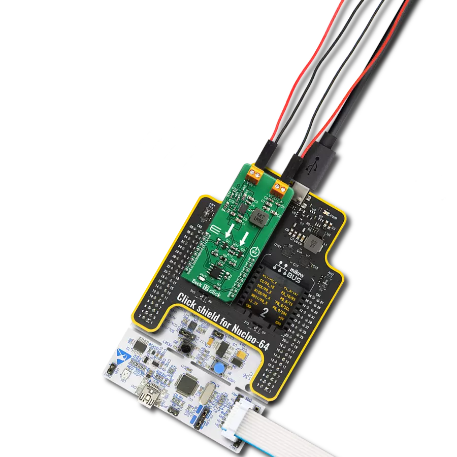
Buck 18 Click
Dev. board
Curiosity PIC32 MZ EF
Compiler
NECTO Studio
MCU
PIC32MZ2048EFM100
Keep systems running longer by optimizing power efficiency in portable and battery-powered devices with precise voltage regulation
A
A
Hardware Overview
How does it work?
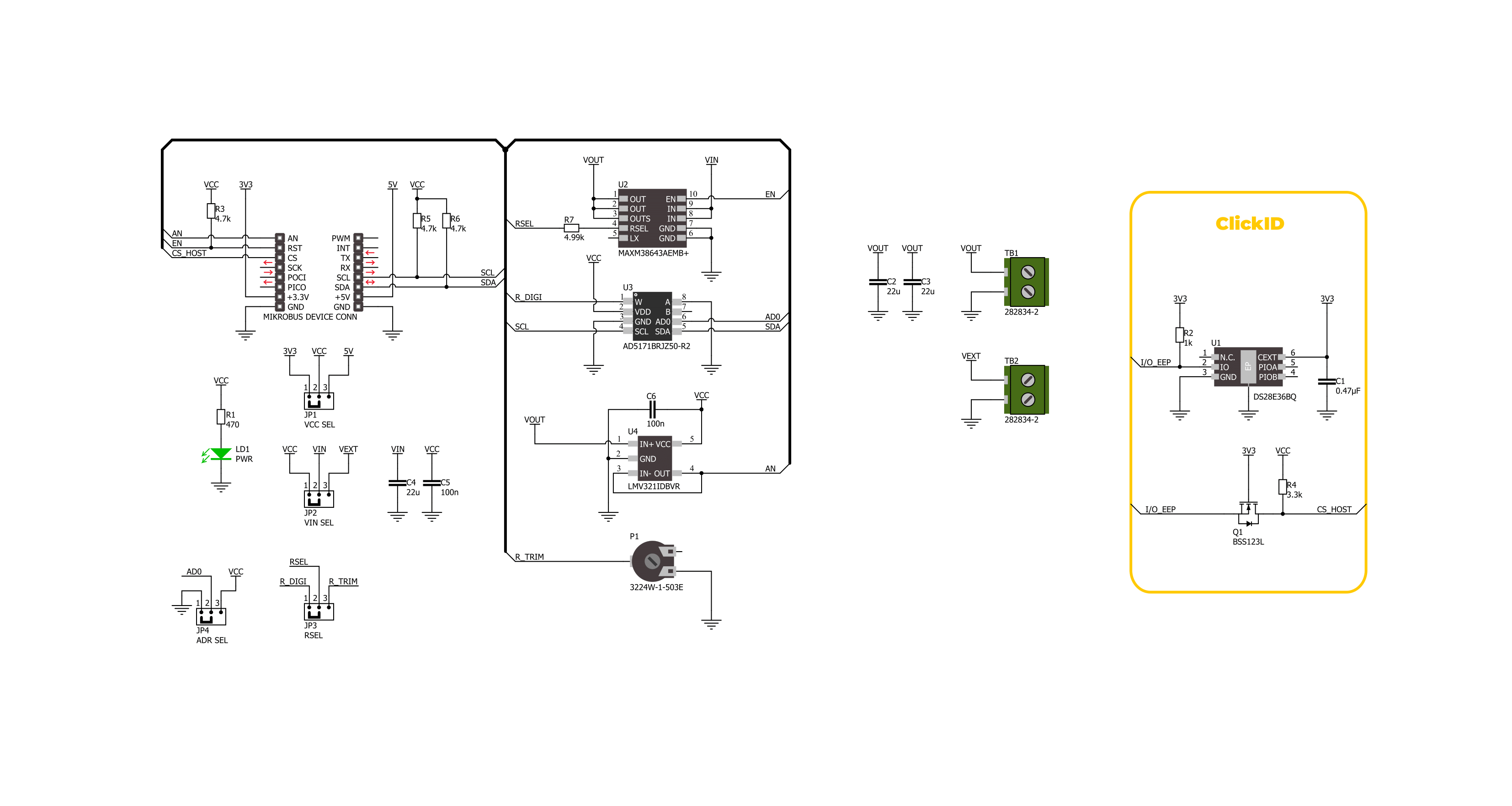
Buck 18 Click is based on the MAXM38643, an ultra-low-IQ (330nA) buck module from Analog Devices. This module efficiently steps down input voltages from 1.8V to 5.5V (supplied via the VEXT terminal) to output voltages between 0.7V and 3.3V on the VOUT terminal. Additionally, the output voltage is accessible through the analog AN pin on the mikroBUS™ socket. Users can manually adjust the output voltage using the onboard TRIM trimmer or digitally via the AD5171 digital potentiometer controlled through the I2C interface. The adjustment method is selected by positioning the RSEL jumper to either DIGI or TRIM. The AD5171 also allows setting its I2C address using the ADDR SEL jumper. This module is designed for optimal performance, automatically switching between ultra-low-power mode (ULPM), low-power mode
(LPM), and high-power mode (HPM) based on the load current, ensuring efficiency and a quick transient response. In ULPM, the module overregulates to enhance efficiency and allows the output capacitor to manage transient load currents up to 600mA. It is particularly well-suited for portable devices, wearables, hearables, ultra-low-power IoT applications, single Li+ and coin cell battery devices, and more. Besides the I2C interface pins, the board also uses the EN pin for control, which functions as the device enable. Setting this pin to a HIGH logic level enables the buck module while setting it to LOW disables the part and puts it into Shutdown mode. Buck 18 Click also offers versatile power sourcing options, allowing users to choose between internal and external supplies to best suit their application
needs. This flexibility is achieved through the VIN SEL jumper, which enables users to select the VCC position for sourcing power internally via the mikroBUS™ power rails or the VEXT position to connect an external power supply. As mentioned, the external power supply can range from 1.8V to 5.5V, providing a broad voltage range for various project requirements. This Click board™ can operate with either 3.3V or 5V logic voltage levels selected via the VCC SEL jumper. This way, both 3.3V and 5V capable MCUs can use the communication lines properly. Also, this Click board™ comes equipped with a library containing easy-to-use functions and an example code that can be used as a reference for further development.

Features overview
Development board
Curiosity PIC32 MZ EF development board is a fully integrated 32-bit development platform featuring the high-performance PIC32MZ EF Series (PIC32MZ2048EFM) that has a 2MB Flash, 512KB RAM, integrated FPU, Crypto accelerator, and excellent connectivity options. It includes an integrated programmer and debugger, requiring no additional hardware. Users can expand
functionality through MIKROE mikroBUS™ Click™ adapter boards, add Ethernet connectivity with the Microchip PHY daughter board, add WiFi connectivity capability using the Microchip expansions boards, and add audio input and output capability with Microchip audio daughter boards. These boards are fully integrated into PIC32’s powerful software framework, MPLAB Harmony,
which provides a flexible and modular interface to application development a rich set of inter-operable software stacks (TCP-IP, USB), and easy-to-use features. The Curiosity PIC32 MZ EF development board offers expansion capabilities making it an excellent choice for a rapid prototyping board in Connectivity, IOT, and general-purpose applications.

Microcontroller Overview
MCU Card / MCU

Architecture
PIC32
MCU Memory (KB)
2048
Silicon Vendor
Microchip
Pin count
100
RAM (Bytes)
524288
Used MCU Pins
mikroBUS™ mapper
Take a closer look
Click board™ Schematic
Step by step
Project assembly

Start by selecting your development board and Click board™. Begin with the Curiosity PIC32 MZ EF as your development board.


Track your results in real time
Application Output
1. Application Output - In Debug mode, the 'Application Output' window enables real-time data monitoring, offering direct insight into execution results. Ensure proper data display by configuring the environment correctly using the provided tutorial.

2. UART Terminal - Use the UART Terminal to monitor data transmission via a USB to UART converter, allowing direct communication between the Click board™ and your development system. Configure the baud rate and other serial settings according to your project's requirements to ensure proper functionality. For step-by-step setup instructions, refer to the provided tutorial.

3. Plot Output - The Plot feature offers a powerful way to visualize real-time sensor data, enabling trend analysis, debugging, and comparison of multiple data points. To set it up correctly, follow the provided tutorial, which includes a step-by-step example of using the Plot feature to display Click board™ readings. To use the Plot feature in your code, use the function: plot(*insert_graph_name*, variable_name);. This is a general format, and it is up to the user to replace 'insert_graph_name' with the actual graph name and 'variable_name' with the parameter to be displayed.

Software Support
Library Description
This library contains API for Buck 18 Click driver.
Key functions:
buck18_set_vout- This function sets the voltage output level.buck18_read_voltage- This function reads raw ADC value and converts it to proportional voltage level.buck18_enable- This function turns on the power switch and enables the buck mode.
Open Source
Code example
The complete application code and a ready-to-use project are available through the NECTO Studio Package Manager for direct installation in the NECTO Studio. The application code can also be found on the MIKROE GitHub account.
/*!
 * @file main.c
 * @brief Buck 18 Click Example.
 *
 * # Description
 * This example demonstrates the use of the Buck 18 Click board by changing the output voltage.
 *
 * The demo application is composed of two sections :
 *
 * ## Application Init
 * Initialization of I2C module and log UART.
 * After driver initialization, the app executes a default configuration.
 *
 * ## Application Task
 * The demo application changes the output voltage and displays the current voltage output value.
 * Results are being sent to the UART Terminal, where you can track their changes.
 *
 * @author Nenad Filipovic
 *
 */

#include "board.h"
#include "log.h"
#include "buck18.h"

static buck18_t buck18;   /**< Buck 18 Click driver object. */
static log_t logger;    /**< Logger object. */

void application_init ( void )
{
    log_cfg_t log_cfg;  /**< Logger config object. */
    buck18_cfg_t buck18_cfg;  /**< Click config object. */

    /**
     * Logger initialization.
     * Default baud rate: 115200
     * Default log level: LOG_LEVEL_DEBUG
     * @note If USB_UART_RX and USB_UART_TX
     * are defined as HAL_PIN_NC, you will
     * need to define them manually for log to work.
     * See @b LOG_MAP_USB_UART macro definition for detailed explanation.
     */
    LOG_MAP_USB_UART( log_cfg );
    log_init( &logger, &log_cfg );
    log_info( &logger, " Application Init " );

    // Click initialization.
    buck18_cfg_setup( &buck18_cfg );
    BUCK18_MAP_MIKROBUS( buck18_cfg, MIKROBUS_1 );
    err_t init_flag = buck18_init( &buck18, &buck18_cfg );
    if ( ( ADC_ERROR == init_flag ) || ( I2C_MASTER_ERROR == init_flag ) )
    {
        log_error( &logger, " Communication init." );
        for ( ; ; );
    }

    if ( BUCK18_ERROR == buck18_default_cfg ( &buck18 ) )
    {
        log_error( &logger, " Default configuration." );
        for ( ; ; );
    }

    log_info( &logger, " Application Task " );
}

void application_task ( void )
{
    for ( buck18_vout_t vout = BUCK18_VOUT_3V3; vout <= BUCK18_VOUT_0V9; vout++ )
    {
        if ( BUCK18_OK == buck18_set_vout( &buck18, vout ) )
        {
            float voltage = 0;
            if ( BUCK18_OK == buck18_read_voltage( &buck18, &voltage ) )
            {
                log_printf( &logger, " Voltage : %.3f[V]\r\n\n", voltage );
                Delay_ms ( 1000 );
                Delay_ms ( 1000 );
                Delay_ms ( 1000 );
                Delay_ms ( 1000 );
                Delay_ms ( 1000 );
            }
        }
    }
}

int main ( void )
{
    /* Do not remove this line or clock might not be set correctly. */
    #ifdef PREINIT_SUPPORTED
    preinit();
    #endif

    application_init( );

    for ( ; ; )
    {
        application_task( );
    }

    return 0;
}

// ------------------------------------------------------------------------ END