Reach new heights with MPL3115A2 and PIC32MZ2048EFM100
Measure height relative to sea level or ground level

Published Feb 01, 2024
Click board™
Altitude Click
Dev. board
Curiosity PIC32 MZ EF
Compiler
NECTO Studio
MCU
PIC32MZ2048EFM100
Provide accurate measurements of the current altitude or elevation of an object or location with high resolution and reliability
A
A
Hardware Overview
How does it work?
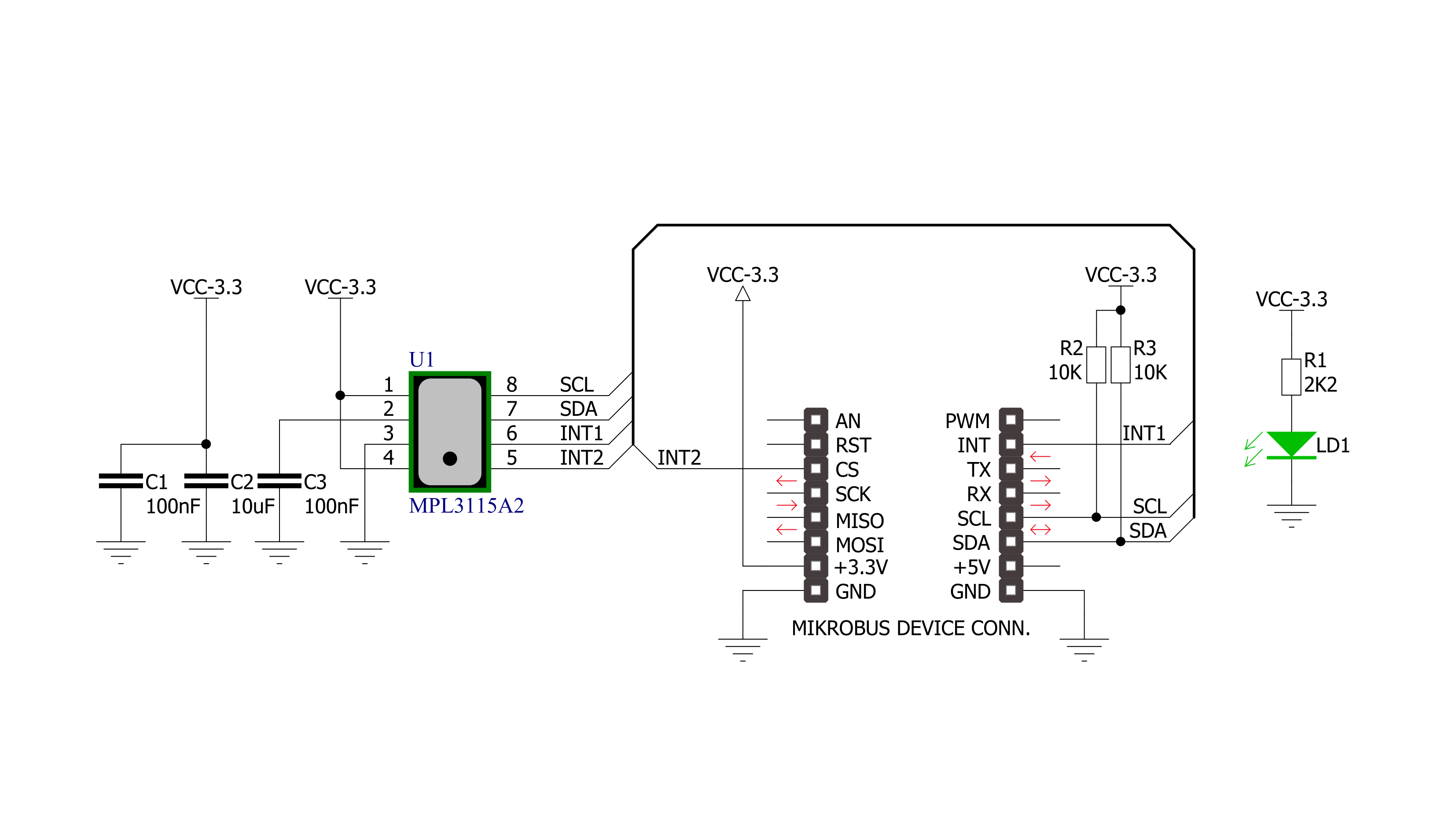
Altitude Click is based on the MPL3115A2, a low-power, high-accuracy digital output altimeter, barometer, and thermometer from NXP Semiconductors. A high-resolution 24-bit ADC digitizes the MPL3115A2 outputs; it provides 20-bit pressure/altitude and 12-bit temperature data with an altitude resolution of 30cm. Pressure output can be resolved with output in fractions of a Pascal and altitude in fractions of a meter. The high stability of both pressure and temperature signals makes it suitable for accurate altimetry in various applications. The MPL3115A2 contains automatic internal data processing with data acquisition and compensation, which removes compensation tasks from the host MCU, and a 32-sample FIFO buffer to minimize the overhead of collecting multiple data
samples. Numerous user-programmable, power-saving, and interrupt modes are available, including programmed acquisition cycle timing and poll-only modes. It can also autonomously collect data at programmed intervals and store it for up to 12 days, depending on the data acquisition rate (1 second - 9 hours). This Click board™ communicates with MCU using the standard I2C 2-Wire interface with a maximum clock frequency of 400kHz. The MPL3115A2 also features two independently programmable interrupt signals, IT1 and IT2, routed to the INT and CS pins on the mikroBUS™ socket, entirely programmed by the user through the I2C interface (functions, threshold, and the timing of the interrupt pins). These can be set to generate an interrupt signal when a new set
of pressure/altitude and temperature data is available, simplifying data acquisition for the host MCU. It can also be configured to generate interrupts when a user-programmed set of conditions are met, such as when a single new data acquisition is ready, when a desired number of samples are stored within the internal FIFO, or when a change of pressure/altitude or temperature is detected. This Click board™ can only be operated with a 3.3V logic voltage level. The board must perform appropriate logic voltage level conversion before using MCUs with different logic levels. However, the Click board™ comes equipped with a library containing functions and an example code that can be used as a reference for further development.

Features overview
Development board
Curiosity PIC32 MZ EF development board is a fully integrated 32-bit development platform featuring the high-performance PIC32MZ EF Series (PIC32MZ2048EFM) that has a 2MB Flash, 512KB RAM, integrated FPU, Crypto accelerator, and excellent connectivity options. It includes an integrated programmer and debugger, requiring no additional hardware. Users can expand
functionality through MIKROE mikroBUS™ Click™ adapter boards, add Ethernet connectivity with the Microchip PHY daughter board, add WiFi connectivity capability using the Microchip expansions boards, and add audio input and output capability with Microchip audio daughter boards. These boards are fully integrated into PIC32’s powerful software framework, MPLAB Harmony,
which provides a flexible and modular interface to application development a rich set of inter-operable software stacks (TCP-IP, USB), and easy-to-use features. The Curiosity PIC32 MZ EF development board offers expansion capabilities making it an excellent choice for a rapid prototyping board in Connectivity, IOT, and general-purpose applications.

Microcontroller Overview
MCU Card / MCU

Architecture
PIC32
MCU Memory (KB)
2048
Silicon Vendor
Microchip
Pin count
100
RAM (Bytes)
524288
Used MCU Pins
mikroBUS™ mapper
Take a closer look
Click board™ Schematic
Step by step
Project assembly

Start by selecting your development board and Click board™. Begin with the Curiosity PIC32 MZ EF as your development board.


Track your results in real time
Application Output
1. Application Output - In Debug mode, the 'Application Output' window enables real-time data monitoring, offering direct insight into execution results. Ensure proper data display by configuring the environment correctly using the provided tutorial.

2. UART Terminal - Use the UART Terminal to monitor data transmission via a USB to UART converter, allowing direct communication between the Click board™ and your development system. Configure the baud rate and other serial settings according to your project's requirements to ensure proper functionality. For step-by-step setup instructions, refer to the provided tutorial.

3. Plot Output - The Plot feature offers a powerful way to visualize real-time sensor data, enabling trend analysis, debugging, and comparison of multiple data points. To set it up correctly, follow the provided tutorial, which includes a step-by-step example of using the Plot feature to display Click board™ readings. To use the Plot feature in your code, use the function: plot(*insert_graph_name*, variable_name);. This is a general format, and it is up to the user to replace 'insert_graph_name' with the actual graph name and 'variable_name' with the parameter to be displayed.

Software Support
Library Description
This library contains API for Altitude Click driver.
Key functions:
altitude_generic_single_write- Generic Single Write functionaltitude_generic_multiple_read- Generic Multiple Read functionaltitude_get_altitude- Altitude Get function
Open Source
Code example
The complete application code and a ready-to-use project are available through the NECTO Studio Package Manager for direct installation in the NECTO Studio. The application code can also be found on the MIKROE GitHub account.
/*!
 * \file main.c
 * \brief Altitude Click example
 *
 * # Description
 * This is a example which demonstrates the use of Altitude Click board.
 * This demo example offers the altitude [m], pressure [mbar] and temperature
 * [deg C] measurements from sensor.
 *
 * The demo application is composed of two sections :
 *
 * ## Application Init
 * Initializes I2C driver and all used pins, performs a default configuration
 * for Altitude Click board and initializes the uart console for results
 * logging.
 *
 * ## Application Task
 * Shows two different uses of sensor, altimeter and barometer mode.
 * Reads the altitude, pressure and temperature results in standard units and
 * sends this results to the console.
 *
 * \author Nemanja Medakovic
 *
 */
// ------------------------------------------------------------------- INCLUDES

#include "board.h"
#include "log.h"
#include "altitude.h"


// ------------------------------------------------------------------ VARIABLES

static altitude_t altitude;
static log_t console;

// ------------------------------------------------------ APPLICATION FUNCTIONS

void application_init( void )
{
    altitude_cfg_t altitude_cfg;
    log_cfg_t log_cfg;

    //  Click initialization.
    altitude_cfg_setup( &altitude_cfg );
    ALTITUDE_MAP_MIKROBUS( altitude_cfg, MIKROBUS_1 );
    altitude_init( &altitude, &altitude_cfg );
    altitude_default_cfg( &altitude );

    /**
     * Logger initialization.
     * Default baud rate: 115200
     * Default log level: LOG_LEVEL_DEBUG
     * @note If USB_UART_RX and USB_UART_TX
     * are defined as HAL_PIN_NC, you will
     * need to define them manually for log to work.
     * See @b LOG_MAP_USB_UART macro definition for detailed explanation.
     */
    LOG_MAP_USB_UART( log_cfg );
    log_init( &console, &log_cfg );
    log_printf( &console, "***  Altitude initialization done  ***\r\n" );
    log_printf( &console, "**************************************\r\n" );
}

void application_task( void )
{
    float altitude_result;
    float pressure_result;
    float temperature_result;

    //  Altimeter sensor mode for altitude data reading.
    altitude_set_sensor_mode( &altitude, ALTITUDE_SENSMOD_ALTIMETER );
    Delay_ms( 100 );

    while ( 0 == altitude_get_drdy_status( &altitude, ALTITUDE_STATUS_FLAG_PDR ) );

    altitude_result = altitude_get_altitude( &altitude );

    //  Barometer sensor mode for pressure data reading.
    altitude_set_sensor_mode( &altitude, ALTITUDE_SENSMOD_BAROMETER );
    Delay_ms( 100 );

    while ( 0 == altitude_get_drdy_status( &altitude, ALTITUDE_STATUS_FLAG_PDR ) );

    pressure_result = altitude_get_pressure( &altitude );
    temperature_result = altitude_get_temperature( &altitude );

    log_printf( &console, "** Altitude is %.2f m\r\n", altitude_result );
    log_printf( &console, "** Pressure is %.2f mbar\r\n", pressure_result );
    log_printf( &console, "** Temperature is %.2f Celsius\r\n", temperature_result );
    log_printf( &console, "**************************************\r\n" );
}

void main( void )
{
    application_init( );

    for ( ; ; )
    {
        application_task( );
    }
}

// ------------------------------------------------------------------------ END


