Ensure your data remains secure with the PN7120 and PIC32MZ2048EFM100 combo
Discover the 'Near' in Near Field Communication - NFC at your fingertips

Published Oct 19, 2023
Click board™
NFC Click
Dev. board
Curiosity PIC32 MZ EF
Compiler
NECTO Studio
MCU
PIC32MZ2048EFM100
With NFC, your world is just a touch away, and we invite you to embrace the NFC experience for a more connected and convenient lifestyle
A
A
Hardware Overview
How does it work?
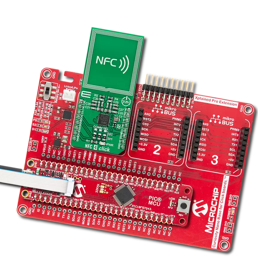
NFC Click is based on the PN7120, a full NFC forum-compliant controller with integrated firmware and NCI interface from NXP Semiconductors. The PN7120 implements the RF and all the low-level functionality, like an antenna driving and receiver circuitry, to realize an NFC Forum-compliant reader. It utilizes an outstanding modulation and demodulation concept for different contactless communication methods and protocols. The PN7120 fully complies with many Reader/Writer standards like ISO 14443A/B up to 848 kBit/s in under 25% of ASK modulation. The NFC Click fully complies with the NFC Forum specifications, meaning it can behave as an NFC reader, a tag, or to establish a two-way connection with another NFC device. For this purpose, the NFC Click can work in several modes. In card emulation mode, it behaves like a smart card or a
tag. It does not initiate communication; it only responds to an NFC reader. The Read/Write mode makes the NFC Click behave as an NFC reader, where it can communicate with a passive tag, smart card, or an NFC device that operates in a card emulation mode. Peer-to-Peer mode establishes a two-way communication channel between a pair of NFC-enabled devices. The NFC Click uses a standard 2-Wire I2C interface to communicate with the host MCU and supports standard mode (100MHz), fast mode (400KHz), and high-speed mode (3.4MHz). The I2C address can be selected via the ADDR SEL jumper with 0 set by default. The PN7120 has two types of integrated memory: RAM and EEPROM. Internal registers of the PN7120 store configuration data, while the RF configuration for dedicated RF protocols is defined by EEPROM data,
copied by a command issued from the host MCU. This allows users to achieve maximum RF performance from a given antenna design. In addition to the I2C interface signals, this board uses several other signals from the mikroBUS™ socket. The reset pin routed on the RST pin of the mikroBUS™ socket provides the general reset ability, while the IRT pin of the mikroBUS™ socket represents an interrupt request to inform the host controller of various events. This Click board™ can be operated only with a 3.3V logic voltage level. The board must perform appropriate logic voltage level conversion before using MCUs with different logic levels. Also, it comes equipped with a library containing functions and an example code that can be used as a reference for further development.


Features overview
Development board
Curiosity PIC32 MZ EF development board is a fully integrated 32-bit development platform featuring the high-performance PIC32MZ EF Series (PIC32MZ2048EFM) that has a 2MB Flash, 512KB RAM, integrated FPU, Crypto accelerator, and excellent connectivity options. It includes an integrated programmer and debugger, requiring no additional hardware. Users can expand
functionality through MIKROE mikroBUS™ Click™ adapter boards, add Ethernet connectivity with the Microchip PHY daughter board, add WiFi connectivity capability using the Microchip expansions boards, and add audio input and output capability with Microchip audio daughter boards. These boards are fully integrated into PIC32’s powerful software framework, MPLAB Harmony,
which provides a flexible and modular interface to application development a rich set of inter-operable software stacks (TCP-IP, USB), and easy-to-use features. The Curiosity PIC32 MZ EF development board offers expansion capabilities making it an excellent choice for a rapid prototyping board in Connectivity, IOT, and general-purpose applications.

Microcontroller Overview
MCU Card / MCU

Architecture
PIC32
MCU Memory (KB)
2048
Silicon Vendor
Microchip
Pin count
100
RAM (Bytes)
524288
Used MCU Pins
mikroBUS™ mapper
Take a closer look
Click board™ Schematic

Step by step
Project assembly

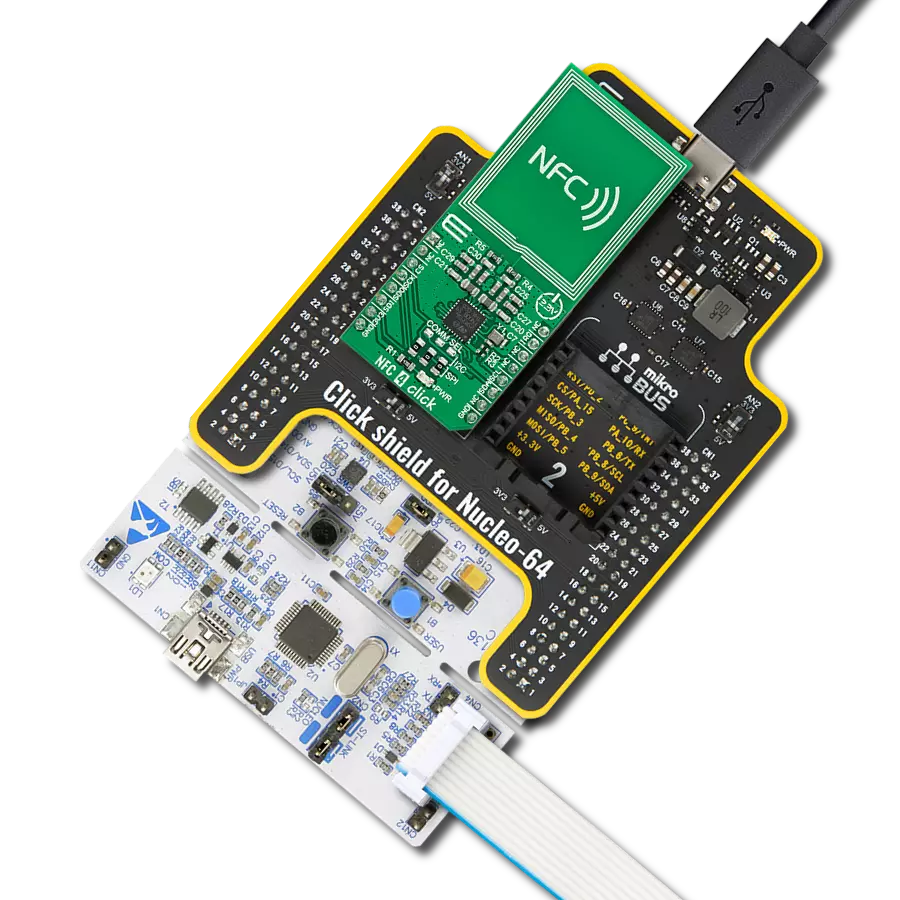
Start by selecting your development board and Click board™. Begin with the Curiosity PIC32 MZ EF as your development board.


Track your results in real time
Application Output
1. Application Output - In Debug mode, the 'Application Output' window enables real-time data monitoring, offering direct insight into execution results. Ensure proper data display by configuring the environment correctly using the provided tutorial.

2. UART Terminal - Use the UART Terminal to monitor data transmission via a USB to UART converter, allowing direct communication between the Click board™ and your development system. Configure the baud rate and other serial settings according to your project's requirements to ensure proper functionality. For step-by-step setup instructions, refer to the provided tutorial.

3. Plot Output - The Plot feature offers a powerful way to visualize real-time sensor data, enabling trend analysis, debugging, and comparison of multiple data points. To set it up correctly, follow the provided tutorial, which includes a step-by-step example of using the Plot feature to display Click board™ readings. To use the Plot feature in your code, use the function: plot(*insert_graph_name*, variable_name);. This is a general format, and it is up to the user to replace 'insert_graph_name' with the actual graph name and 'variable_name' with the parameter to be displayed.

Software Support
Library Description
This library contains API for NFC Click driver.
Key functions:
nfc_hw_reset- HW reset function.nfc_get_data- Get data function.nfc_cmd_disable_standby_mode- Disable standby mode command function.
Open Source
Code example
The complete application code and a ready-to-use project are available through the NECTO Studio Package Manager for direct installation in the NECTO Studio. The application code can also be found on the MIKROE GitHub account.
/*!
 * @file main.c
 * @brief NFC Click example
 *
 * # Description
 * This is an example which demonstrates the usage of NFC Click board.
 *
 * The demo application is composed of two sections :
 *
 * ## Application Init
 * Initializes driver and logger, then performs hardware reset, puts the device in operating mode by
 * disabling standby mode, performs test procedure, and configures the device to start discovery.
 *
 * ## Application Task
 * NFC Click board can be used for detection of RFiD tag
 * and displays it's value via USART terminal.
 * All data logs write on USB uart changes for every 1 sec.
 *
 * Additional Functions :
 *  -void display_packet ( control_packet_t *ctrl_pck ) - Display packet log data.
 *  -void display_nfc_data ( control_packet_t *ctrl_pck ) - Display packet log data.
 *  -void nfc_read_nfc_data ( nfc_t *ctx, control_packet_t *ctrl_pck ) - Read nfc data function.
 *  -void nfc_test_antenna ( nfc_t *ctx, control_packet_t *ctrl_pck ) - Testing Antenna function.
 *
 * @author Stefan Ilic
 *
 */

#include "board.h"
#include "log.h"
#include "nfc.h"

static nfc_t nfc;
static log_t logger;
uint8_t n_cnt;

control_packet_t ctrl_pck_data;

/**
 * @brief NFC display packet function.
 * @details This function displays data values.
 */
void display_packet ( control_packet_t *ctrl_pck );

/**
 * @brief NFC display tag info.
 * @details This function displays tag info data.
 */
void nfc_print_info (  control_packet_t *ctrl_pck );

/**
 * @brief NFC display nfc data function.
 * @details This function displays nfc data values.
 */
void display_nfc_data ( control_packet_t *ctrl_pck );

/**
 * @brief NFC read nfc data function.
 * @details This function reads nfc data and displays data.
 */
void nfc_read_nfc_data ( nfc_t *ctx, control_packet_t *ctrl_pck );

/**
 * @brief NFC test antena function.
 * @details This function tests antenna and displays data.
 */
void nfc_test_antenna ( nfc_t *ctx, control_packet_t *ctrl_pck );

void application_init ( void )
{
    log_cfg_t log_cfg;  /**< Logger config object. */
    nfc_cfg_t nfc_cfg;  /**< Click config object. */

    /**
     * Logger initialization.
     * Default baud rate: 115200
     * Default log level: LOG_LEVEL_DEBUG
     * @note If USB_UART_RX and USB_UART_TX
     * are defined as HAL_PIN_NC, you will
     * need to define them manually for log to work.
     * See @b LOG_MAP_USB_UART macro definition for detailed explanation.
     */
    LOG_MAP_USB_UART( log_cfg );
    log_init( &logger, &log_cfg );
    log_info( &logger, " Application Init " );

    // Click initialization.
    nfc_cfg_setup( &nfc_cfg );
    NFC_MAP_MIKROBUS( nfc_cfg, MIKROBUS_1 );
    err_t init_flag = nfc_init( &nfc, &nfc_cfg );
    if ( I2C_MASTER_ERROR == init_flag )
    {
        log_error( &logger, " Application Init Error. " );
        log_info( &logger, " Please, run program again... " );

        for ( ; ; );
    }

    log_printf( &logger, "        HW Reset       \r\n" );
    nfc_hw_reset( &nfc );
    Delay_ms ( 100 );

    log_printf( &logger, "-----------------------\r\n" );
    log_printf( &logger, " Reset and Init. Core  \r\n" );
    nfc_cmd_core_reset( &nfc );
    Delay_ms ( 100 );

    nfc_read_ctrl_packet_data( &nfc, &ctrl_pck_data );
    Delay_ms ( 100 );

    nfc_cmd_core_init( &nfc );
    Delay_ms ( 100 );

    nfc_read_ctrl_packet_data( &nfc, &ctrl_pck_data );
    Delay_ms ( 100 );
    display_packet( &ctrl_pck_data );

    while ( nfc_check_irq( &nfc ) == NFC_IRQ_STATE_HIGH );

    log_printf( &logger, "-----------------------\r\n" );
    log_printf( &logger, " Disabling Standby Mode \r\n" );
    nfc_cmd_disable_standby_mode( &nfc );
    Delay_ms ( 100 );

    nfc_read_ctrl_packet_data( &nfc, &ctrl_pck_data );
    Delay_ms ( 100 );
    display_packet( &ctrl_pck_data );

    nfc_test_antenna( &nfc, &ctrl_pck_data );

    log_printf( &logger, "-----------------------\r\n" );
    log_printf( &logger, "Starting Test Procedure\r\n" );
    nfc_cmd_test_procedure( &nfc );
    Delay_ms ( 100 );

    nfc_read_ctrl_packet_data( &nfc, &ctrl_pck_data );
    Delay_ms ( 100 );
    display_packet( &ctrl_pck_data );

    nfc_hw_reset( &nfc );
    Delay_ms ( 100 );

    log_printf( &logger, "-----------------------\r\n" );
    log_printf( &logger, "       NFC Config.     \r\n" );
    nfc_default_cfg ( &nfc, &ctrl_pck_data );

    log_printf( &logger, "-----------------------\r\n" );
    log_printf( &logger, "     Discovery Start   \r\n" );
    nfc_cmd_start_discovery( &nfc );
    Delay_ms ( 100 );

    nfc_read_ctrl_packet_data( &nfc, &ctrl_pck_data );
    Delay_ms ( 100 );
    display_packet( &ctrl_pck_data );

    log_printf( &logger, "-----------------------\r\n" );
    log_printf( &logger, "-------- START --------\r\n" );
    log_printf( &logger, "-----------------------\r\n" );
    Delay_ms ( 500 );

    log_info( &logger, " Application Task " );
}

void application_task ( void )
{
    while ( nfc_check_irq( &nfc ) == NFC_IRQ_STATE_HIGH )
    {
        nfc_read_nfc_data ( &nfc, &ctrl_pck_data );
    }

    while ( nfc_check_irq( &nfc ) == NFC_IRQ_STATE_LOW );

    log_printf( &logger, "-----------------------\r\n" );
    Delay_ms ( 1000 );
}

int main ( void )
{
    /* Do not remove this line or clock might not be set correctly. */
    #ifdef PREINIT_SUPPORTED
    preinit();
    #endif

    application_init( );

    for ( ; ; )
    {
        application_task( );
    }

    return 0;
}

void display_packet ( control_packet_t *ctrl_pck )
{
    log_printf( &logger, "- - - - - - - - - - - -\r\n" );
    log_printf( &logger, " Message Type   = %d\r\n", ( uint16_t ) ctrl_pck->message_type );
    log_printf( &logger, " Pck Bound Flag = %d\r\n", ( uint16_t ) ctrl_pck->pck_bound_flag );
    log_printf( &logger, " Group Ident    = %d\r\n", ( uint16_t ) ctrl_pck->group_ident );
    log_printf( &logger, " Opcode Ident   = %d\r\n", ( uint16_t ) ctrl_pck->opcode_ident );
    log_printf( &logger, " Payload Length = %d\r\n", ( uint16_t ) ctrl_pck->payload_length );
    log_printf( &logger, "- - - - - - - - - - - -\r\n" );

    for ( n_cnt = 0; n_cnt < ctrl_pck_data.payload_length; n_cnt++ )
    {
        log_printf( &logger, " Payload[ %.2d ]  = 0x%.2X\r\n", ( uint16_t ) n_cnt, ( uint16_t ) ctrl_pck_data.payload[ n_cnt ]  );
    }

    log_printf( &logger, "- - - - - - - - - - - -\r\n" );
    memset( ctrl_pck_data.payload, 0x00, 255 );
}

void nfc_print_info ( control_packet_t *ctrl_pck )
{
    log_printf( &logger, "    NFC Tag info    \r\n" );
    log_printf( &logger, "- - - - - - - - - - - -\r\n" );
    log_printf( &logger, " Serial number = %.2X:%.2X:%.2X:%.2X\r\n",
                ( uint16_t ) ctrl_pck_data.payload[ 10 ], ( uint16_t ) ctrl_pck_data.payload[ 11 ],
                ( uint16_t ) ctrl_pck_data.payload[ 12 ], ( uint16_t ) ctrl_pck_data.payload[ 13 ] );
    log_printf( &logger, " ATQA = 0x%.2X%.2X\r\n",  ( uint16_t ) ctrl_pck_data.payload[ 8 ],
                ( uint16_t ) ctrl_pck_data.payload[ 9 ]  );
    log_printf( &logger, " SAK = 0x%.2X\r\n",  ( uint16_t ) ctrl_pck_data.payload[ 15 ]  );

}

void display_nfc_data ( control_packet_t *ctrl_pck )
{
    log_printf( &logger, "- - - - - - - - - - - -\r\n");
    log_printf( &logger, " Read Block:\r\n");

    for ( n_cnt = 0; n_cnt < ctrl_pck->payload_length; n_cnt++ )
    {
        log_printf( &logger, "\t 0x%.2X \r\n", ( uint16_t ) ctrl_pck->payload[ n_cnt ] );
    }
    log_printf( &logger, "\t 0x%.2X \r\n", ( uint16_t ) ctrl_pck->payload[ ctrl_pck->payload_length - 2 ] );

    log_printf( &logger, "- - - - - - - - - - - -\r\n" );
    memset( ctrl_pck->payload, 0x00, 255 );
}

void nfc_read_nfc_data ( nfc_t *ctx, control_packet_t *ctrl_pck )
{
    nfc_read_ctrl_packet_data( ctx, ctrl_pck );
    nfc_print_info( ctrl_pck );
    Delay_ms ( 100 );

    nfc_activate_rmt_mifare_card( ctx );
    Delay_ms ( 100 );
    nfc_read_ctrl_packet_data( ctx, ctrl_pck );
    Delay_ms ( 10 );

    while ( nfc_check_irq( ctx ) == NFC_IRQ_STATE_LOW );

    nfc_read_ctrl_packet_data( ctx, ctrl_pck );
    nfc_cmd_authenticate_sector( ctx, 0x30 );
    Delay_ms ( 100 );
    nfc_read_ctrl_packet_data( ctx, ctrl_pck );
    Delay_ms ( 10 );

    while ( nfc_check_irq( ctx ) == NFC_IRQ_STATE_LOW );

    nfc_read_ctrl_packet_data( ctx, ctrl_pck );
    display_nfc_data( ctrl_pck );
    log_printf( &logger, "    Disconnect Card    \r\n" );
    nfc_cmd_card_disconnected( ctx );
    Delay_ms ( 10 );
    nfc_read_ctrl_packet_data( ctx, ctrl_pck );
    Delay_ms ( 10 );

    while ( nfc_check_irq( ctx ) == NFC_IRQ_STATE_LOW );

    nfc_read_ctrl_packet_data( ctx, ctrl_pck );
    Delay_ms ( 100 );
}

void nfc_test_antenna ( nfc_t *ctx, control_packet_t *ctrl_pck )
{
    log_printf( &logger, "-----------------------\r\n" );
    log_printf( &logger, "    Testing Antenna    " );
    nfc_cmd_antenna_test( ctx, 0x01 );
    Delay_ms ( 100 );

    nfc_read_ctrl_packet_data( ctx, ctrl_pck );
    Delay_ms ( 100 );

    nfc_cmd_antenna_test( ctx, 0x07 );
    Delay_ms ( 100 );
    nfc_read_ctrl_packet_data( ctx, ctrl_pck );
    Delay_ms ( 100 );

    nfc_cmd_antenna_test( ctx, 0x0F );
    Delay_ms ( 100 );
    nfc_read_ctrl_packet_data( ctx, ctrl_pck );
    Delay_ms ( 100 );
    display_packet( ctrl_pck );
}
// ------------------------------------------------------------------------ END