Collect and transmit data across vast distances with RN2903 and PIC32MZ2048EFM100
915MHz long-range transceivers: Your bridge to the future

Published Nov 09, 2023
Click board™
LR 2 Click
Dev. board
Curiosity PIC32 MZ EF
Compiler
NECTO Studio
MCU
PIC32MZ2048EFM100
With our 915MHz transceiver, you can unlock new possibilities in agriculture, environmental monitoring, and industrial control, thanks to their exceptional range and penetration capabilities.
A
A
Hardware Overview
How does it work?
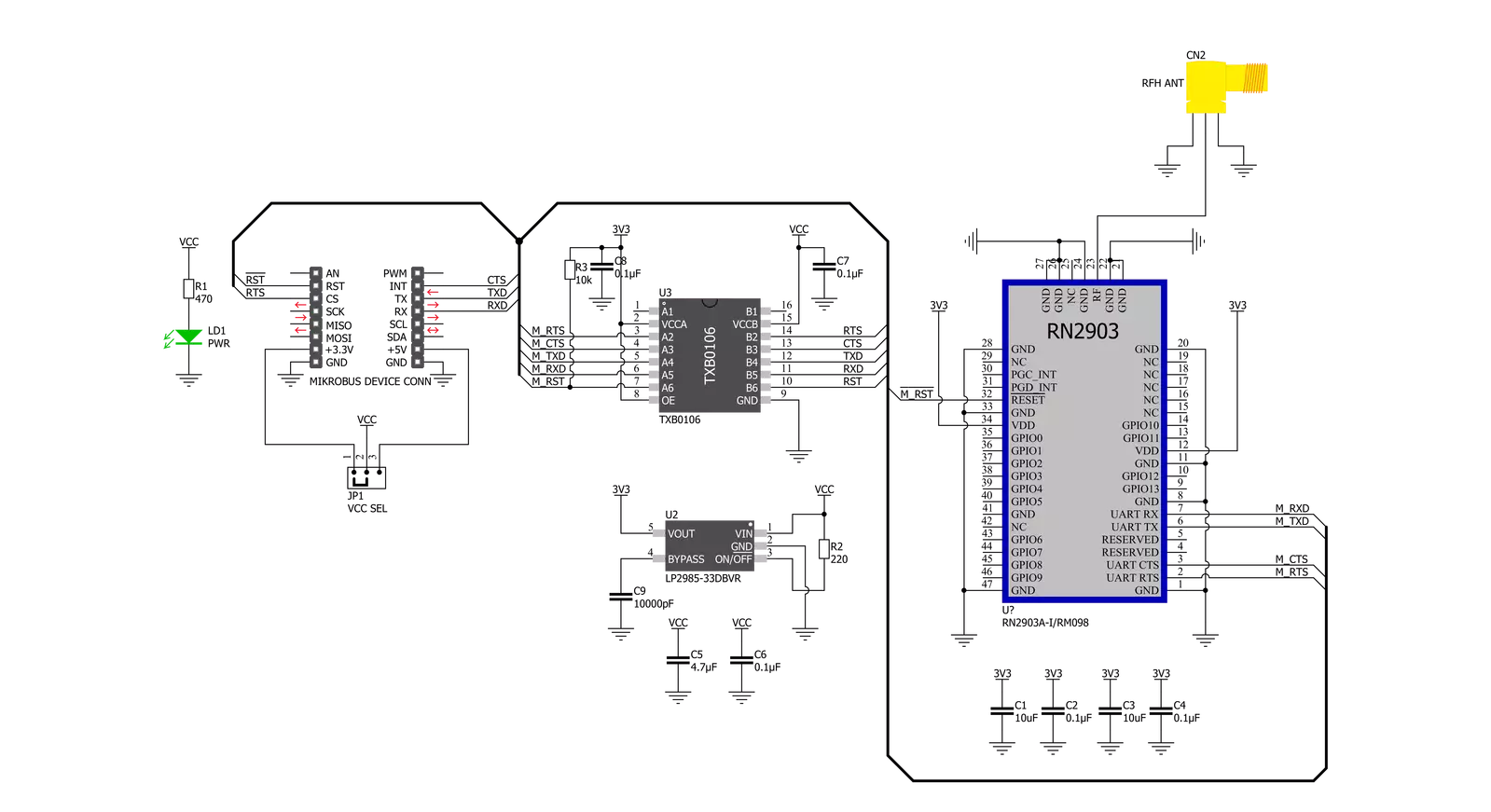
LR 2 Click is based on the RN2903, a low-power, long-range RF technology-based transceiver module from Microchip Technology. It features the Class A LoRaWAN compliant stack, optimized for robust LoRaWAN networking, immune to interferences, and suitable for long-range wireless operation. It offers a long-range spread spectrum communication with high interference immunity. A receiver with a sensitivity of -148dBm combined with the 18.5dBm integrated amplifier allows for extended range links that can achieve up to 15km in an open area (by the module manufacturer specification). This Click board™ offers data rates of 300kbps with FSK modulation and 12500bps with LoRa Technology modulation and is associated with the 915MHz ISM band suitable for applications in the United States, Canada, Australia, and New Zealand. To join a LoRaWAN network, the RN2903 requires a LoRaWAN concentrator/gateway. The endpoint device has to
use a unique endpoint address, an application session key, and a network session key. The first method is called over-the-air activation (OTAA), where these keys are issued after a specific join procedure. The second method is to assign these keys manually, using UART commands. This method is called activation by personalization (ABP) and can be prone to some security issues. In any case, before an end device can communicate on the LoRaWAN network, it must be activated. LR 2 Click communicates with MCU using the UART interface with commonly used UART RX and TX pins, including the hardware flow control pins CTS and RTS (Clear to Send, Ready to Send) at data rates up to 57600bps for the data transfer. There are three groups of commands used to configure and operate the separate layers of the RN2903 (SYSTEM, MAC, and RADIO). Each layer controls a specific area of the module, and every UART command starts with one of the three keywords,
which represent an abbreviation of the layer name they are controlling. The module also has a non-volatile memory (EEPROM) for storing the configuration settings and some additional data. Also, this Click board™ can be reset through the Hardware Reset pin, labeled as RST on the mikroBUS™ socket, by setting this pin to a low logic state. LR 2 Click features the SMA antenna connector with an impedance of 50Ω, so it can be equipped with the appropriate 915MHz compliant antenna that MIKROE offers. This Click board™ can operate with either 3.3V or 5V logic voltage levels selected via the VCC SEL jumper. This way, both 3.3V and 5V capable MCUs can use the communication lines properly. Also, this Click board™ comes equipped with a library containing easy-to-use functions and an example code that can be used as a reference for further development.

Features overview
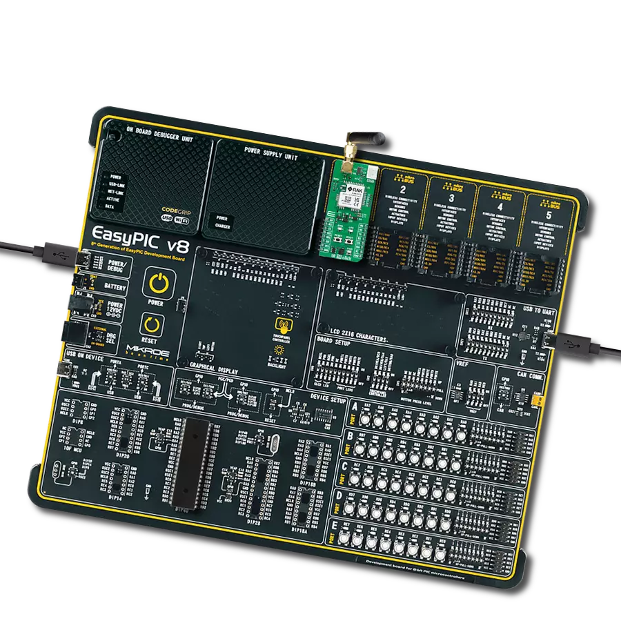
Development board
Curiosity PIC32 MZ EF development board is a fully integrated 32-bit development platform featuring the high-performance PIC32MZ EF Series (PIC32MZ2048EFM) that has a 2MB Flash, 512KB RAM, integrated FPU, Crypto accelerator, and excellent connectivity options. It includes an integrated programmer and debugger, requiring no additional hardware. Users can expand
functionality through MIKROE mikroBUS™ Click™ adapter boards, add Ethernet connectivity with the Microchip PHY daughter board, add WiFi connectivity capability using the Microchip expansions boards, and add audio input and output capability with Microchip audio daughter boards. These boards are fully integrated into PIC32’s powerful software framework, MPLAB Harmony,
which provides a flexible and modular interface to application development a rich set of inter-operable software stacks (TCP-IP, USB), and easy-to-use features. The Curiosity PIC32 MZ EF development board offers expansion capabilities making it an excellent choice for a rapid prototyping board in Connectivity, IOT, and general-purpose applications.

Microcontroller Overview
MCU Card / MCU

Architecture
PIC32
MCU Memory (KB)
2048
Silicon Vendor
Microchip
Pin count
100
RAM (Bytes)
524288
You complete me!
Accessories
Rubber Antenna GSM/GPRS Right Angle is the perfect companion for all GSM Click boards™ in our extensive lineup. This specialized antenna is designed to optimize your wireless connectivity with impressive features. With a wide frequency range spanning 824-894/1710-1990MHz or 890-960/1710-1890MHz, it can handle various frequency bands, ensuring a seamless and reliable connection. The antenna boasts an impedance of 50 Ohms and a gain of 2dB, enhancing signal reception and transmission. Its 70/180MHz bandwidth provides flexibility for diverse applications. The vertical polarization further enhances its performance. With a maximum input power capacity of 50W, this antenna ensures robust communication even under demanding conditions. Measuring a compact 50mm in length and featuring an SMA male connector, the Rubber Antenna GSM/GPRS Right Angle is a versatile and compact solution for your wireless communication needs.

Used MCU Pins
mikroBUS™ mapper
Take a closer look
Click board™ Schematic
Step by step
Project assembly

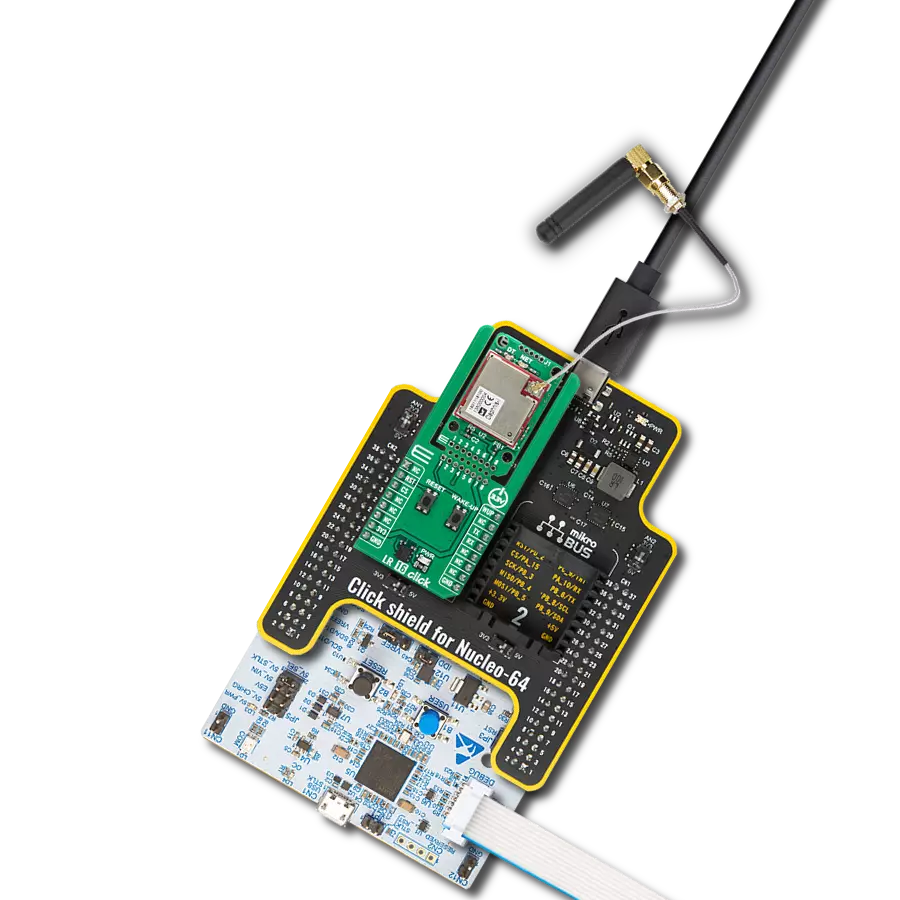
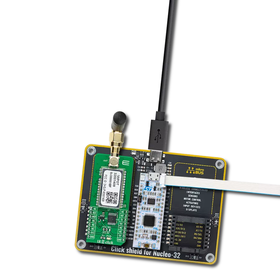
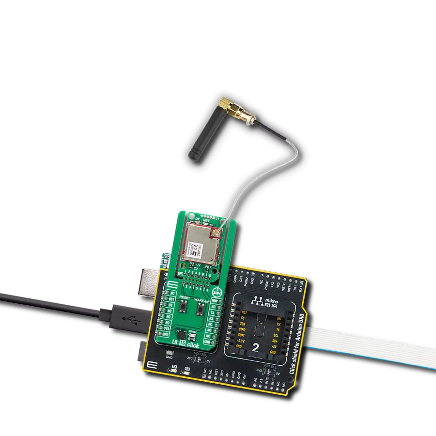
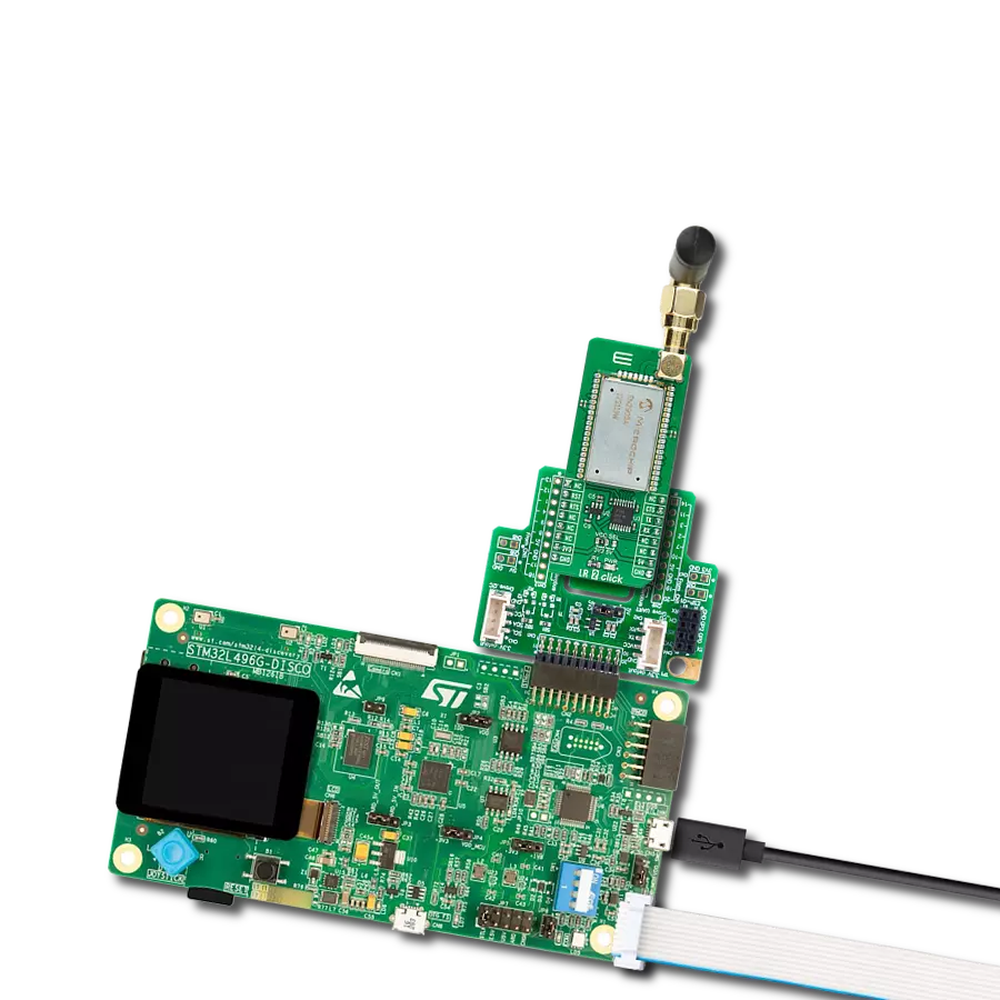
Start by selecting your development board and Click board™. Begin with the Curiosity PIC32 MZ EF as your development board.


Software Support
Library Description
This library contains API for LR 2 Click driver.
Key functions:
lr_mac_tx- Function for writing mac parameterslr_join- Function for setting join modelr_tick_conf- Timer Configuration
Open Source
Code example
The complete application code and a ready-to-use project are available through the NECTO Studio Package Manager for direct installation in the NECTO Studio. The application code can also be found on the MIKROE GitHub account.
/*!
 * @file main.c
 * @brief LR 2 Click Example.
 *
 * # Description
 * This example shows the usage of the LR 2 Click board by transmitting and receiving data.
 *
 * The demo application is composed of two sections :
 *
 * ## Application Init
 * Initializes the driver and performs default configuration and reads System version.
 *
 * ## Application Task
 * Transmitter mode - sends a desired message each second and checks if it is sent successfully.
 * Receiver mode - displays all the received characters on USB UART.
 *
 * @author Stefan Ilic
 *
 */

#include "board.h"
#include "log.h"
#include "lr2.h"
#include "conversions.h"

// Comment out the line below in order to switch the application mode to receiver
#define DEMO_APP_TRANSMITTER

#define PROCESS_COUNTER 5
#define PROCESS_RX_BUFFER_SIZE 300

// ------------------------------------------------------------------ VARIABLES

static lr2_t lr2;
static log_t logger;

uint8_t resp_buf[ 50 ];
uint8_t send_message[ 9 ] = { 'M', 'i', 'k', 'r', 'o', 'E', 13, 10, 0 };

/**
 * @brief LR 2 data reading function.
 * @details This function reads data from device and concatenates data to application buffer.
 * @return Nothing.
 * @note None.
 */
static void lr2_process ( void );

void application_init ( void )
{
    log_cfg_t log_cfg;  /**< Logger config object. */
    lr2_cfg_t lr2_cfg;  /**< Click config object. */

    /**
     * Logger initialization.
     * Default baud rate: 115200
     * Default log level: LOG_LEVEL_DEBUG
     * @note If USB_UART_RX and USB_UART_TX
     * are defined as HAL_PIN_NC, you will
     * need to define them manually for log to work.
     * See @b LOG_MAP_USB_UART macro definition for detailed explanation.
     */
    LOG_MAP_USB_UART( log_cfg );
    log_init( &logger, &log_cfg );
    log_info( &logger, " Application Init " );

    // Click initialization.
    lr2_cfg_setup( &lr2_cfg );
    LR2_MAP_MIKROBUS( lr2_cfg, MIKROBUS_1 );
    if ( UART_ERROR == lr2_init( &lr2, &lr2_cfg ) )
    {
        log_error( &logger, " Communication init." );
        for ( ; ; );
    }

    lr2_default_cfg( &lr2, 0, 0 );
    lr2_process( );

    lr2_cmd( &lr2, LR2_CMD_SYS_GET_VER, resp_buf );
    log_printf( &logger, " System VER: %s \r\n", resp_buf );

    lr2_cmd( &lr2, LR2_CMD_MAC_PAUSE, resp_buf );
    log_printf( &logger, " MAC PAUSE: %s \r\n", resp_buf );

    lr2_cmd( &lr2, LR2_CMD_RADIO_SET_WDT, resp_buf );
    log_printf( &logger, " RADIO SET WDT 0: %s \r\n", resp_buf );

#ifdef DEMO_APP_TRANSMITTER
    log_printf( &logger, " Application Mode: Transmitter\r\n" );
#else
    log_printf( &logger, " Application Mode: Receiver\r\n" );
#endif
    log_info( &logger, " Application Task " );
}

void application_task ( void )
{
    lr2_process( );

#ifdef DEMO_APP_TRANSMITTER
    uint8_t hex_buf[ 50 ] = { 0 };
    uint8_t cnt = 0;
    for ( cnt = 0; cnt < strlen( send_message ); cnt++ )
    {
        uint8_to_hex( send_message[ cnt ], &hex_buf[ cnt * 2 ] );
    }
    if ( LR2_OK == lr2_tx( &lr2, hex_buf ) )
    {
        log_printf( &logger, " Sent message: %s", send_message );
        log_printf( &logger, " Response : %s\r\n", resp_buf );
    }
    Delay_ms ( 1000 );
#else
    if ( LR2_OK == lr2_rx( &lr2, LR2_ARG_0, resp_buf ) )
    {
        uint8_t text_buf[ 20 ] = { 0 };
        uint8_t hex_buf[ 3 ] = { 0 };
        uint8_t cnt = 0;
        for ( cnt = 0; cnt < ( strlen( resp_buf ) - 10 ); cnt += 2 )
        {
            hex_buf[ 0 ] = resp_buf[ 10 + cnt ];
            hex_buf[ 1 ] = resp_buf[ 11 + cnt ];
            text_buf[ cnt / 2 ] = hex_to_uint8( hex_buf );
        }
        log_printf( &logger, "Received message: %s\r\n", text_buf );
    }
#endif
}

int main ( void )
{
    /* Do not remove this line or clock might not be set correctly. */
    #ifdef PREINIT_SUPPORTED
    preinit();
    #endif

    application_init( );

    for ( ; ; )
    {
        application_task( );
    }

    return 0;
}

static void lr2_process ( void )
{
    int32_t rsp_size;

    char uart_rx_buffer[ PROCESS_RX_BUFFER_SIZE ] = { 0 };
    uint8_t check_buf_cnt;
    uint8_t process_cnt = PROCESS_COUNTER;

    while ( process_cnt != 0 )
    {
        rsp_size = lr2_generic_read( &lr2, uart_rx_buffer, PROCESS_RX_BUFFER_SIZE );

        if ( rsp_size > 0 )
        {
            // Validation of the received data
            for ( check_buf_cnt = 0; check_buf_cnt < rsp_size; check_buf_cnt++ )
            {
                lr2_put_char( &lr2, uart_rx_buffer[ check_buf_cnt ] );
                lr2_isr_process( &lr2 );
            }

            // Clear RX buffer
            memset( uart_rx_buffer, 0, PROCESS_RX_BUFFER_SIZE );
        }
        else
        {
            process_cnt--;

            // Process delay
            Delay_ms ( 100 );
        }
    }
}

// ------------------------------------------------------------------------ END
Additional Support
Resources
Category:LoRa